Advertisement
Quick Links
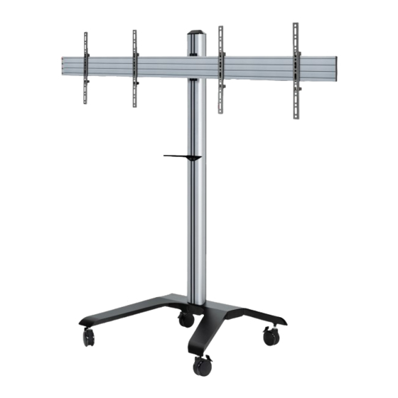
BT8514
UNIVERSAL
TWIN SCREEN VC Trolley
INSTALLATION GUIDE
SPECIFICATIONS
• Recommended for mounting two screens side-by-side
up to: 46" (116cm)
• Max load: 40kg (per screen)
• Suitable for displays with VESA
fixings up to 400 x 400mm
• Includes VC shelf which mounts directly to the column
• Non-marking locking / braked castors included
• Integrated cable management
• Dimensions: H.1905mm W.1504mm D.863mm
®
& non-VESA
www.btechavmounts.com
Advertisement

Related Manuals for B-Tech BT8514


Summary of Contents for B-Tech BT8514
- Page 1 BT8514 UNIVERSAL TWIN SCREEN VC Trolley INSTALLATION GUIDE SPECIFICATIONS • Recommended for mounting two screens side-by-side up to: 46" (116cm) • Max load: 40kg (per screen) ® • Suitable for displays with VESA & non-VESA fixings up to 400 x 400mm •...
-
Page 2: Table Of Contents
Please check carefully to make sure there are no missing or defective parts - defective parts must never be used. B-Tech AV Mounts, its distributors and dealers are not liable or responsible for damage or injury caused by improper installation, improper use or failure to observe these safety instructions. In such cases, all guarantees will expire. -
Page 4: Parts List
BT8514 PARTS LIST PLEASE KEEP THIS FOR FUTURE REFERENCE... - Page 5 PART NAME BASE CASTOR COLUMN JOINING PLATE 1.5M HORIZONTAL RAIL END CAPS INTERFACE ARM VC SHELF TRIM COLUMN CAP COLUMN STRIPS REAR COLUMN COVERS M8 x 35mm CSK SCREW M8 x 10mm SCREW SLIDING NUT M8 x 12mm SCREW M8 x 12mm CSK SCREW M4 x 10mm SCREW UNC 1/4"...
-
Page 6: Installation Instructions
INSTALLATION INSTRUCTIONS FIX CASTORS TO BASE Screw 4 x item 2 into item 1 and apply the brakes. ATTACH COLUMN TO BASE Stand item 1 in its upright position. Insert item 3 into the cut out in item 1. Screw 4 x item 12 through the underside of item 1 into item 3. - Page 7 ATTACH JOINING PLATE TO COLUMN Slide 4 x item 14 into item 3 (2 in each front slot). Attach item 4 to item 3 by fixing item 13 into item 14. INSERT SLIDING NUTS AND ADD SCREWS TO RAIL i. Insert 2 x item 4 into the top and bottom slots of item 5. Position the nuts centrally on item 5 and set the horizontal row 150mm apart.
- Page 8 HOOK RAIL ONTO COLUMN Hook the item 5 onto item 4 and fix in place with item 16. FIX INTERFACE ARMS TO SCREENS Fix items 6 to the back of the screen using the interface kit (items A-M). Note: Ensure items 6 are positioned the correct way round and the same holes are used on both interface arms.
- Page 9 HOOK ON SCREENS Hook screens onto item 5. SCREEN SCREEN Note: Ensure castors are set in the braked position SCREEN Note: Ensure arms are hooked securely onto the rail...
- Page 10 LEVEL SCREENS (OPTIONAL) HEIGHT ADJUSTMENT SCREWS Use the top screws on item 6 to level the height of the screens. HEIGHT ADJUSTMENT SCREWS HEIGHT ADJUSTMENT SCREW LOCK SCREENS ONTO RAIL On both screens, tighten the safety screws on the bottom of item 6, securing the screens to item 5.
- Page 11 ATTACH VC SHELF TO COLUMN i. Attach item 7 to item 3 using items 13 & 14. ii. Use items 17 or 18 to fix a camera onto item 7. VC CAMERA...
- Page 12 ATTACH PLASTIC COVERS i. Fit item 5 to the ends of item 5. i. Attach item 11 to the rear of item 3. ii. Fit item 9 to the top of item 3. iii. Fit item 8 into front and rear of item 1. INSERT COLUMN STRIPS Insert item 10 into the front slots on item 3.
- Page 13 CABLE MANAGEMENT Route cables through bottom of item 1. Cut-outs in item 9 can be used for cable management. Cables can be routed through the cut-outs in item 9. Cut-outs for cable management Cut-outs in item 1 can be used for cable management CABLE Warning!
-
Page 14: Product Dimensions
PLEASE KEEP THIS FOR FUTURE REFERENCE 1500mm FRONT VIEW 400mm 400mm 28mm 8.4mm 122mm 61mm BACK VIEW 30mm THESE INSTRUCTIONS ARE INTENDED AS A GUIDE ONLY AND B-TECH ACCEPTS NO LIABILITY FOR THE ACCURACY OF THE INFORMATION CONTAINED IN THIS DOCUMENT. - Page 15 PLEASE KEEP THIS FOR FUTURE REFERENCE 146.2mm SIDE VIEW 36mm 480.9mm 270.8mm 869.2mm TOP VIEW 120mm 1504mm THESE INSTRUCTIONS ARE INTENDED AS A GUIDE ONLY AND B-TECH ACCEPTS NO LIABILITY FOR THE ACCURACY OF THE INFORMATION CONTAINED IN THIS DOCUMENT.
-
Page 16: B-Tech Contact Details
©2020 B-Tech AV Mounts. All rights reserved. B-Tech AV Mounts is a division of B-Tech International Design and Manufacturing Limited. B-Tech AV Mounts and the B-Tech logo are registered trade marks. All other brands and product names are trademarks of their respective owners.
Need help?
Do you have a question about the BT8514 and is the answer not in the manual?
Questions and answers