Advertisement
Quick Links
Bar Lights
LDLB/LDLB-IP Series
Instruction Guide
Thank you for purchasing a CCS product. To ensure proper use of
the product, please read this instruction guide before use and keep
it for your future reference.
Features
These LED Light Units feature integrated light control and ON/OFF control circuits.
The LEDs are driven with a constant-current system and the light is set to any of 100 levels with variable-current control.
You can change between Constant Lighting Mode and Overdrive Mode.
You can manually set the light intensity from the operating panel or set it with an analog input (0 to 10 V) from an external device.
You can daisy-chain up to three Light Units to provide power and externally control the light intensity of all of the Light Units together.
The LDLB-IP Series provides IP67 water resistance.
1
Important Information for Equipment Safety
This product has been designed with full consideration of safety. However, incorrect usage of the product may result in
fire, electric shock, or other serious accidents. Observe the following precautions.
The following symbols are used in this Instruction Guide to indicate
and classify the relative importance of warnings and cautions.
Indicates that incorrect
Indicates that incorrect
Warning
us age may re sult in
usage may result in injury
Caution
serious injury or death.
or property damage.
The following symbols indicate and classify the precautions in the
Instruction Guide.
PROHIBITED
DISASSEMBLY
MANDATORY
DO NOT TOUCH
DO NOT SUBJECT
PROHIBITED
ACTIONS
WITH WET HANDS
TO MOISTURE
These symbols indicate
This symbol indicates
prohibited actions.
required actions.
Warning
D o n o t d i s a s s e m b l e
LED light radiation may
or modify the product.
cause corneal or retinal
Doing so may result in
a b n o r m a l i t i e s i f y o u
MANDATORY
DISASSEMBLY
ACTIONS
fire or electric shock.
PROHIBITED
look directly at the light.
To prevent harmful light
exposure, never look
directly at the LED light.
D o n o t c o n n e c t o r
This product generates
high temperatures. Do
disconnect the Light
not touch the product
Unit and cables with
while it is turned on or
wet hands. Doing so
immediately after it is
MANDATORY
DO NOT TOUCH
may result in electric
ACTIONS
WITH WET HANDS
turned of f, or burning
shock.
m a y r e s u l t . P r o v i d e
c o o lin g w it h a f an o r
other ventilation if the
product is to be used in
a closed space.
U s i n g L D L B - s e r i e s
Connect or disconnect
Light Units (not water
the light cable only after
resistant)
tur ning of f t he p ower
MANDATORY
M a k e s u r e t h a t t h e
s u p p l y. Fa i l u r e t o d o
DO NOT SUBJECT
ACTIONS
TO MOISTURE
product is free of moisture
so may result in circuit
or any liquid. Exposure to
d a m a g e , f i r e c a u s e d
water may result in fire,
by a minute spark, or
electric shock.
electric shock.
If abnormal condition occurs such as fuming, heat, smell,
noise, or so on, stop using the product immediately, and
turn off the power supply. A fire or electric shock may
MANDATORY
ACTIONS
result if the product is kept used.
4
Connections
Before you connect the Input Cable or Link Cable, make sure that the power supply is turned OFF. Making connec-
Warning
tions with the power supply turned ON may result in fire, electric shock, or breakdown in the Light Unit.
Connecting One Light Unit
Connect the Input Cable to the input connector and connect the leads on the end of the Input
1
Cable to an external device.
Turn ON the power supply.
2
Daisy-chaining Two or Three Light Units
You can daisy-chain up to three Light Units to set the light intensities or turn ON and OFF all of the Light Units together.
Connect the output and input connectors of the Light Units with Link Cables. Also connect the Input
1
Cable to the input connector and connect the leads on the end of the Input Cable to an external device.
Light Unit A
Light Unit B
Sealing Cap
(for LDLB-IP Series)
Turn ON the power supply.
2
Link Cable
Set the operating modes of the Light Units.
3
When you daisy-chain Light Units, you must use the operating panel on each Light Unit to change between Constant
Lighting Mode and Overdrive Mode. Use the following procedure to change the operating mode.
Changing from Constant Lighting Mode to Overdrive Mode
1) Set the ON/OFF inputs from the external device to the status for turning ON the Light Unit in Constant Lighting Mode.
Refer to 7. ON/OFF Inputs for information on the ON/OFF input.
2) Change the operating modes in order from the Light Unit that is farthest from the power supply.
(In the above figure, the order would be Light Unit A, Light Unit B, and then Light Unit C.)
Refer to 3. Names and Functions of Parts for information on changing the operating mode. If the setting status of the
ON/OFF inputs is not correct, an overdrive error will occur when you change the operating mode. Also, if the order is not
correct, an overload error will occur.
Changing from Overdrive Mode to Constant Lighting Mode
1) Change the operating modes in order from the Light Unit that is nearest to the power supply.
(In the above figure, the order would be Light Unit C, Light Unit B, and then Light Unit A.)
Refer to 3. Names and Functions of Parts for information on changing the operating mode. If the order is not correct,
an overload error will occur. The setting status of the ON/OFF inputs is not relevant.
Maximum Cable Length
The maximum length of the 24-VDC power supply cable depends on the wire diameter, operating mode, and number of con-
nected Light Units. The maximum cable lengths are given in the following table.
One Light Unit Connected: The table gives the maximum length of the Input Cable.
Two or Three Light Units Connected: The table gives the maximum total length of the Input Cable and Link Cables.
Number of Light Units connected in Constant Lighting Mode
Wire diameter
1
2
AWG16
10 m
10 m
AWG18
10 m
10 m
AWG20
10 m
10 m
AWG22
10 m
7 m
* The wire diameter is AWG22 for the optional (sold separately) FECB-M12-5F-series Input Cables and FECB-0.6-M12-5M-5F Link Cable. If the
maximum length given above is exceeded, shorten the Input Cable or contact CCS.
Using LDLB-IP-series Light Units
Observe the following precautions to prevent electrical shock and accidents from water entry.
Handle the Light Units and connectors with care. Do not deform or damage the connectors.
Connect the cables correctly to the Light Units.
Caution
Connect a Sealing Cap to any output connectors to which a cable is not connected to maintain water resistance. The
Sealing Cap is connected to the output connector when the Light Unit is shipped.
If the Light Unit is not used for a long period of time with the cable disconnected, attach the Cap to the connector or take
other measures to maintain water resistance.
All manuals and user guides at all-guides.com
- Read Before Use -
Caution
Do not drop the product
Do not bundle product
or subject it to impact.
cables with highvoltage
Doing so may cause the
lines or power lines.
product to malfunction.
Doing so may cause the
PROHIBITED
product to malfunction.
Allow leeway between
t h e c a b l e s w h e n
installing them.
B e c a r e f u l o f s t a t i c
B e f o r e m o v i n g t h e
e l e c t r i c i t y. D a m a g e
p r o d u c t , d i s c o n n e c t
to the LED light may
all connecting cables.
o c c u r , i f a p e r s o n
Damaging the cables
PROHIBITED
c h a r g e d w i t h s t a t i c
m ay r e s u l t i n f i r e o r
electricity touches it.
electric shock.
Keep the product away
from all items charged
with static electricity.
Do not bend a c able
Always hold onto the
past its natural bending
plug or connector when
radius or jam a cable
d i s c o n n e c t i n g t h e
PROHIBITED
i nt o a n a r r o w s p a c e
cables. Pulling on the
w h e n w i r i n g t h e
cable may damage the
product. Doing so may
cable and result in fire
cause product failure.
or electric shock.
D o n o t i n t e n t i o n a l l y
If there is dust or other
s h o r t - c i r c u i t t h e
foreign mat ter on the
positive and negative
elec t ro des, tur n O FF
output terminals.
the power supply and
PROHIBITED
t h e n u s e a d r y c l o t h
to remove the dust or
foreign matter. Failure to
do so may result in fire.
B e s u r e t o u s e t h e
Do not wipe the product
p r o d u c t w i t h i n t h e
with organic solvent s,
range of input voltage.
such as paint thinner or
A pplying the voltage
benzene. Discoloration
PROHIBITED
beyond the range may
or deterioration of the
cause product failure.
product surfaces may
occur.
To external device
Input Cable
Sealing Cap
(for LDLB-IP Series)
Light Unit C
Input Cable
To external device
Link Cable
Number of Light Units connected in Overdrive Mode
3
1
2
10 m
10 m
5.5 m
10 m
8 m
3.5 m
1.5 m
7 m
5.5 m
2 m
Cannot be used.
4.5 m*
3 m*
1 m*
Cannot be used.*
2
Confirming Product Information
The following label is attached to the LED light. The color of the label indicates the luminescence color of the product. The name
label specifies the model name, power consumption, and serial number. Be sure to check the contents before using the product
and handle the label with care. If the label is missing or damaged and the contents cannot be checked, please contact CCS Inc.
Label (Example)
Name label (Example)
3
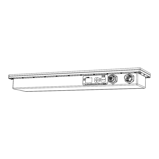
Names and Functions of Parts
Mode Indicator
MANDATORY
Digital Display
ACTIONS
Operating
Panel
The digital display shows the light in-
tensity between 00 and 99.
("00" is the minimum light level.)
You can manually set the light intensity
MANDATORY
ACTIONS
with the + and − switches. Refer to 5.
Setting the Light Intensity on the Oper-
ating Panel for details.
You can change the operating mode
by holding down the + and − switches
at the same time for 3 seconds.
Constant Lighting Mode
MANDATORY
You can set the light intensity to any of
ACTIONS
100 levels from the operating panel or with
an analog input from the input connector.
You can turn the light ON and OFF with an
ON/OFF input from the input connector.
Overdrive Mode
The mode indicator on the operating
panel will light. A larger current en-
MANDATORY
ACTIONS
ables a brighter light intensity (100 lev-
els) than in Constant Lighting Mode.
However, the light intensities that you
can set are restricted as shown below.
Refer to 7. ON/OFF Inputs for details.
Operating time
Signal repeat period to light the LEDs
PROHIBITED
The general relationship between the light intensity and the radiant quantity is shown in the following table.
Light intensity
00
Constant Lighting Mode
10%
Radiant
quantity
Overdrive Mode
100% 102%
5
Setting the Light Intensity on the Operating Panel
If pin 5 (analog input) and pin 3 (common ground) are not connected on the input connector or if 13 to 24 V (maximum in-
put voltage: 26.4) is input, you can use the + and − switches on the operating panel to manually set the light intensity.
MODE
O/D
L
E
Con
V
E
L
OverDrive
Continuous
: Hold down
Digital display
+ switch
The light intensity is displayed on the digital display between 00 and 99
(100 levels).
If you hold down the + or − key for more than 1 second, the value will
change faster.
The manually set light intensity is saved internally even after you turn
OFF the power supply or after you change to external light intensity
control with an analog input.
6
External Control of the Light Intensity
If 0 to 10 V is applied between pin 5 (analog input) and pin 3 (common ground) on the input connector, you can set the light
intensity to any of 100 levels with the voltage of the analog input.
The light intensity is displayed on the digital display between 00 and 99 (100 levels).
Note: The digital display will show "--" if the light is turned OFF in Constant Lighting Mode. If you turn the light ON and OFF repeatedly over
a short period of time, the digital display may not display numbers correctly.
To maintain the light intensity, continue to input a constant voltage. The light intensity that is set by the analog input is not
stored in the Light Unit.
Note: Depending on the number of connected Light Units and the cable length, different light intensities may be set for the same analog
input voltage.
Connection Example
External Circuit
*
Variable power supply
(0 to 10 VDC)
3
2 m
* You can adjust the light intensity with a variable power supply or a variable resistor.
If you use a variable power supply, use a power supply with a sinking
output of 3 mA minimum per Light Unit.
If you use a variable resistor, use the one specified below.
One Light Unit: 15 kΩ
Two Light Units: 10 kΩ
Three Light Units: 5 kΩ
Do not exceed an allowable difference of 20% in the overall resistance.
Note: According to product specifications, the light intensity that is set on
the operating panel may be used when the resistance is near the
maximum value.
- 1 -
(Top panel)
Note: There are no restrictions in the installation
direction. You can install the Light Unit up-
side down or in any other direction. Refer to
10. Dimensions for the installation holes.
Light-emitting Surface
Output Connector (M12 Socket)
Input Connector (M12 Plug)
If you daisy-chain Light Units, this
This connector is used to supply
connector is connected to the input
power to the Light Unit and to input
connector on the next Light Unit with
signals to control the light intensity
a Link Cable.
and turn the light ON and OFF.
A Link Cable (model: FECB-0.6-M12-
Input Cables (models: FECB-M12-5F
5M-5F, 0.6 m) is available as an option
Series, 1, 2, 3, and 5 m, flying leads) are
(sold separately).
available as options (sold separately).
The LDLB-IP-series Light Units maintain IP67
The LDLB-IP-series Light Units maintain IP67
water resistance when this Cable is connected.
water resistance when this Cable is connected.
5
Using LDLB- IP- series
Light Units
4
3
4
If you do not use this con-
nector, always attach a
1
Sealing Cap to it to main-
2
1
tain water resistance.
Refer to 9. Optional Products (Sold Sep-
Pin
No.
arately) for details on the Link Cable.
If you daisy-chain Light Units, you can
supply power, control the light intensity
with an analog input, and use an ON/
OFF input to control all of the Light Units
together. You can also control the light
intensity of the Light Units individually
from the operating panels. You can con-
nect up to three Light Units.
Refer to 6. External Control of the
Light Intensity for information on the
analog input.
01
...
49
50
...
98
99
Refer to 7. ON/OFF Inputs for informa-
tion on the ON/OFF inputs.
11%
...
55%
55%
...
99%
100%
Refer to 9. Optional Products (Sold Sepa-
...
214% 216%
...
328% 330%
rately) for details on the Input Cable.
Input Connector (M12 Plug) Configuration
− switch
Pin
No.
1
2
ON/OFF input (NPN)
3
4
ON/OFF input (PNP)
5
Analog input (0 to 10 V)
Setting the Light Intensity with an Analog Input
LDLB Light Unit
99
79
24 VDC
59
Pin 5
40
20
0
Pin 3
Voltage (V) between Pin 5 and 3
5
3
2
Cable
FECB-M12-
Signal
5F Series
Wire color
1
24 VDC
Brown
2
ON/OFF input (NPN)
White
3
Common ground
Blue
4
ON/OFF input (PNP)
Black
5
Analog input (0 to 10 V)
Gray
5
4
3
1
2
Cable
FECB-M12-
Signal
5F Series
Wire color
24 VDC
Brown
White
Common ground
Blue
Black
Gray
2
4
6
8
10
Advertisement

Related Manuals for CCS LDLB Series


Summary of Contents for CCS LDLB Series
- Page 1 Be sure to check the contents before using the product Instruction Guide and handle the label with care. If the label is missing or damaged and the contents cannot be checked, please contact CCS Inc. Label (Example) (Top panel) Thank you for purchasing a CCS product.
- Page 2 CCS maintains the copyright on this Instruction Guide. Unauthorized transfer or reproduction is strictly prohibited. LDLB-300SW-N White 6100 K Instruction Guide and Dimensional Diagrams in PDF or CAD can be downloaded from the CCS website. http://www.ccs-grp.com LDLB-300RD-N 630 nm Address any product queries to the following address or to your nearest CCS representative.
Need help?
Do you have a question about the LDLB Series and is the answer not in the manual?
Questions and answers