
Subscribe to Our Youtube Channel
Related Manuals for Rtelligent R Series


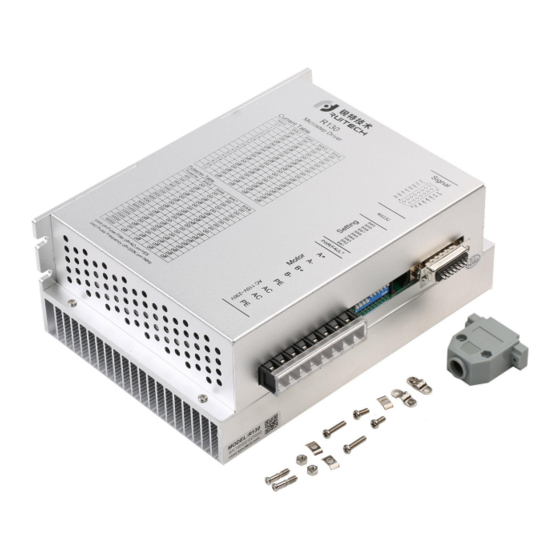
Summary of Contents for Rtelligent R Series
- Page 1 R130 User Manual Digital Stepper Driver R130 User Manual Shenzhen Rtelligent Mechanical Electrical Technology Co.,ltd szruitech.com...
-
Page 2: Table Of Contents
R130 User Manual Contents 1. Product overview...........................1 2. Application environment and installation.................. 2 2.1Environmental requirement.....................2 2.2Driver installation dimensions....................2 2.3Driver installation requirements....................3 3. Driver port and connection......................3 3.1 Port function description......................3 3.2 Power supply input......................... 4 3.3 Motor connection.......................4 3.4 Control signal connection......................5 3.4.1 PUL, DIR Port: connection for pulse command............5 3.4.2 ENA port: enable/disable.................... -
Page 3: Product Overview
1. Product overview Thank you for choosing Rtelligent R series digital stepper driver. R series stepper driver, which surpasses the performance of common analog stepper driver comprehensively based on the new 32-bit DSP platform developed by TI, and adopting the micro-stepping technology and PID current control algorithm design. -
Page 4: Application Environment And Installation
R130 User Manual 2. Application environment and installation 2.1 Environmental requirement Item Rtelligent R130 Installation environment Avoid dust, oil and corrosive environment 0.5G(4.9m/s2) Max Vibration Operating temperature/humidity 0℃ ~ 45℃ / 90% RH or less (no condensation) Storage and transportation -10℃... -
Page 5: Driver Installation Requirements
R130 User Manual 2.3 Driver installation requirements Please install the driver vertically or horizontally, with its front facing forward, top facing upward to facilitate cooling. During assembly, avoid drillings and other foreign matters falling inside the driver. During assembly, please use M3 screw to fix. When there is vibration source (such as a driller) close to the installation position, please use a vibrating absorber or a vibration resistant rubber gasket. -
Page 6: Power Supply Input
R130 User Manual IN1+ Universal input 1 IN1- 3.3 ~ 24V level Input signal compatible IN2+ Universal input 2 IN2- ALM+ Alarm Output ALM- 24V, below Output signal 40mA RDY+ Ready output RDY- No definition 3.2 Power supply input The driver's working power is AC power, and the input voltage range is between 110V ~ 230V. -
Page 7: Control Signal Connection
3.4 Control signal connection 3.4.1 PUL, DIR Port: connection for pulse command The signal interface of standard R series driver is pulse-shaped, and the R130 can receive two types of pulse command signals. The upper controller can be the pulse signal generating device, such as PLC, MCU, control card and controller. -
Page 8: Input Io Signal: In1, In2
RDY ready signal output. The alarm state and ready state of the driver can be output to the external upper computer system. The output signal can also be defined as other logic outputs. For specific use, please contact Rtelligent engineers. 3.4.5 Examples for pulse enable signal connection... -
Page 9: The Setting Of Dip Switches And Operating Parameters
R130 User Manual Difference Pul+ Pul+ Pul- Pul- Dir+ Dir+ Driver Controller Dir- Dir- Ena+ Ena+ Ena- Ena- 4. The setting of DIP switches and operating parameters The setting of current The setting of pulse per revolution Filtering Bandwidth 4.1 The setting of current Average Current Remarks 0.7A... -
Page 10: The Setting Of Pulse Per Revolution
R130 User Manual 5.4A 5.8A 6.2A 6.6A 7.0A DIP SW1, SW2, SW3 , SW4 are used to set current which is output from driver to motor. Generally, the current is set to not exceed the rated current of the motor (effective value). If your system has high request to the heating, please decrease the current properly to lower the motor’s heating. -
Page 11: Filter Selection
R130 User Manual 4.3 Filter selection DIP SW9 is used to select the pulse smoothing filter function of the driver. off means that the driver's internal S-type pulse smoothing function is not applied when the driver receives an external command; On means that when the driver receives an external command, the internal S-type pulse smoothing function of the driver is added. -
Page 12: Common Faults And Troubleshooting
R130 User Manual 6. Common faults and troubleshooting Phenomenon Possible situations Solutions Check the power supply circuit for Power indicator is off normal power supply The motor rotor is locked but Pulse signal is weak; increase the the motor does not work signal current to 7-16mA The speed is too slow Select the right micro-stepping... -
Page 13: Guarantee Clause
R130 User Manual Check whether there is any solder Internal resistance between ball due to excessive addition of terminals is too large solder on the wire connections Acceleration and deceleration Reduce command acceleration or time is too short increase Driver filtering parameters The motor is out Motor torque is too low Select the motor with high torque...
Need help?
Do you have a question about the R Series and is the answer not in the manual?
Questions and answers