
Subscribe to Our Youtube Channel
Related Manuals for Rtelligent R60


Summary of Contents for Rtelligent R60
- Page 1 R60 User Manual Digital Stepper Driver R60 User Manual Shenzhen Rtelligent Mechanical Electrical Technology Co.,ltd...
-
Page 2: Table Of Contents
R60 User Manual Contents 1. Product overview............................1 2.Application environment and installation....................2 2.1Environmental requirement........................2 2.2Driver installation dimensions....................... 2 3.Driver port and connection.......................... 3 3.1Port function description........................3 3.2Power supply input..........................3 3.3Motor connection............................ 4 3.4Control signal connection........................5 3.4.1 PUL, DIR port: connection for pulse command................. 5 3.4.2 ENA port: used to enable or disable....................5... -
Page 3: Product Overview
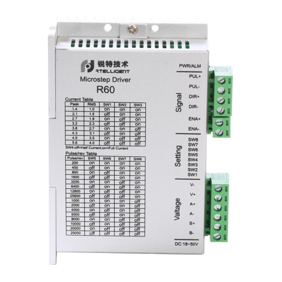
The R60 driver can select the running current and subdivision through the DIP switch. There are 16 subdivisions, 2 acceleration selection, and 8 current selections. It has overvoltage, undervoltage and overcurrent protection. -
Page 4: Application Environment And Installation
R60 User Manual 2. Application environment and installation 2.1 Environmental requirement Item Rtelligent R60 Installation environment Avoid dust, oil and corrosive environment Vibration 0.5G(4.9m/s ) Max Operating temperature/humidity 0℃ ~ 45℃ / 90% RH or less (no condensation) Storage and transportation temperature: -10℃... -
Page 5: Driver Port And Connection
R60 User Manual 2.3 Driver installation requirements Please install the driver vertically or horizontally, with its front facing forward, top facing upward to facilitate cooling. During assembly, avoid drillings and other foreign matters falling inside the driver. During assembly, please use M3 screw to fix. -
Page 6: Motor Connection
8-wire series 8-wire parallel 6线串接 6线中心抽头 6-wire center shaft head 6-wire series The matching motor of the R60 driver is the low resistance and low inductance hybrid stepper motor. The common 2-phase stepper motor’s lead number are 4, 8 and 6. -
Page 7: Control Signal Connection
3.4 Control signal connection 3.4.1 PUL, DIR port: connection for pulse command The standard R series driver signal interface is in the form of pulse, and R60 can receive two kinds of pulse command signals. The upper controller can be the pulse signal generating device, such as PLC, MCU, control card and controller. -
Page 8: Examples For Control Signal Connection
R60 User Manual 3.4.3 Examples for control signal connection Common Anode Pul+ Pul- Dir+ Driver Dir- Controller Ena+ Ena- Common Cathode Pu l+ Pu l- Driver Controller Dir+ Dir- En a + En a - Difference Pul+ Pul+ Pul- Pul-... -
Page 9: The Setting Of Dip Switches And Operating Parameters
R60 User Manual 4.The setting of DIP switches and operating parameters The setting of current Half / Full current option The setting of pulse per revolution 4.1 The setting of current Peak Current Average Current Remarks 1.4A 1.0A 2.1A 1.5A 2.7A... -
Page 10: Half / Full Flow Selection
R60 User Manual DIP SW5, SW6, SW7, and SW8 are used to set the pulse per revolution required by the motor. Motor speed = command pulse frequency / pulse per revolution Motor stroke = number of command pulses / pulse per revolution 4.3 Half / full flow selection... - Page 11 R60 User Manual Check whether the upper computer has Command pulse is incorrect pulse output The rotary direction of motor is Adjust the DIP SW5 reverse The steering of motor is wrong The motor cable is disconnected Check the connection...
-
Page 12: Guarantee Clause
R60 User Manual 7. Guarantee Clause 7.1 Warranty period: 12 months We provide quality assurance for one year from the date of delivery and free maintenance service for our products during the warranty period. 7.2 Exclude the following: ■ Improper connection, such as the polarity of the power supply is reversed and insert/pull the motor connection when the power supply is connected.
Need help?
Do you have a question about the R60 and is the answer not in the manual?
Questions and answers