
Subscribe to Our Youtube Channel
Related Manuals for Rtelligent T60-IO


Summary of Contents for Rtelligent T60-IO
- Page 1 T60-IO User Manual -1- T60-IO Closed Loop Stepper Driver User Manual Shenzhen Rtelligent Mechanical Electrical Technology Co.,ltd szruitech.com...
-
Page 2: Table Of Contents
T60-IO User Manual -2- Contents 1. Product overview ............................3 2.Application environment and installation ....................4 2.1 Environmental requirement ........................4 2.2 Driver installation dimensions ......................5 2.3 Driver installation requirements ......................5 3.Driver port and connection .......................... 6 3.1 Port function description ........................6 3.2 Power supply input ..........................7... -
Page 3: Product Overview
T60-IO User Manual -3- 1. Product overview Thank you for choosing Rtelligent T series digital stepper servo driver. Stepper servo is a stepper motor scheme formed based on the common open loop stepper motor in combination with position feedback and servo algorithm, which features high speed, high torque, high precision, low vibration, low heating and no loss of step. -
Page 4: Application Environment And Installation
T60-IO User Manual -4- T60-IO driver can set subdivision and other parameters through DIP switch and debugging software. It has protection functions such as voltage, current and position, and adds alarm output interface. Its input and output control signals are optically isolated. -
Page 5: Driver Installation Dimensions
T60-IO User Manual -5- 2.2 Driver installation dimensions 2.3 Driver installation requirements Please install the driver vertically or horizontally, with its front facing forward, top facing upward to facilitate cooling. During assembly, avoid drillings and other foreign matters falling inside the driver. -
Page 6: Driver Port And Connection
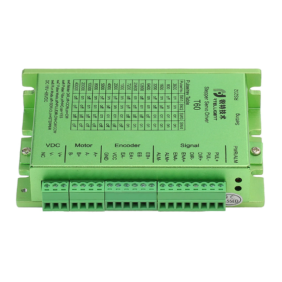
T60-IO User Manual -6- 3. Driver port and connection 3.1 Port function description Function Grade Definition Remarks Input to the positive pole of the DC power supply Power supply DC 24~50V input Input to the negative pole of the DC power... -
Page 7: Power Supply Input
Rtelligent is equipped with a certain length of encoder cable, Please purchase extension cables of different lengths according to the installation needs. 3.4 Motor connection The matching motor of the T60-IO driver is the corresponding T series stepper servo motor, and its szruitech.com... -
Page 8: Control Signal Connection
T60-IO User Manual -8- corresponding motor connection order is fixed and unique. 4-wire motor 4线电机 Yellow Black Green 3.5 Control signal connection 3.5.1 PUL, DIR Port: connection for start and stop command Forward Reverse Not rotate Not rotate 1. At PUL on and DIR off, the motor is triggered to rotate forward.When PUL is turned off, the motor decelerates and stops. -
Page 9: Alm Port: Used For Alarm And Arrival Output
3.5.4 RS232 serial port Symbol Description Positive terminal of power supply RS232 transmitting terminal Ground terminal of power supply RS232 receiving terminal RS232 serial port is used to connect T60-IO debugging software and change other related operating parameters of driver. szruitech.com... -
Page 10: The Setting Of Dip Switches And Operating Parameters
T60-IO User Manual -10- 4. The setting of DIP switches and operating parameters Closed/open loop The setting of speed Motor direction SW6, SW7 are not defined. 4.1 The setting of speed Speed Remarks Other speeds can be customized 1000 1100... -
Page 11: Motor Direction Selection
T60-IO User Manual -11- 4.2 Motor direction selection DIP SW5 is used to set the running direction of the motor under the initial pulse. The “off” means that the motor direction is counterclockwise when inputting the initial pulse; The “on” means that the motor direction is clockwise when inputting the initial pulse. -
Page 12: Common Faults And Troubleshooting
T60-IO User Manual -12- 6. Common faults and troubleshooting Phenomenon Possible situations Solutions Check the power supply circuit for normal Power indicator is off power supply The motor rotor is locked but the Pulse signal is weak; increase the signal... -
Page 13: Appendix A. Guarantee Clause
T60-IO User Manual -13- burned up Check whether there is any solder ball Internal resistance between due to excessive addition of solder on the terminals is too large wire connections Acceleration and deceleration time Reduce command acceleration or is too short...
Need help?
Do you have a question about the T60-IO and is the answer not in the manual?
Questions and answers