
Related Manuals for Rtelligent R110PLUS


Summary of Contents for Rtelligent R110PLUS
- Page 1 R110PLUS USER MANUAL Digital Stepper Driver R110PLUS User Manual Shenzhen Rtelligent Mechanical Electrical Technology Co.,ltd szruitech.com...
-
Page 2: Table Of Contents
R110PLUS USER MANUAL Contents 1. Product overview...........................1 1.1 Characteristic........................... 1 2. Application environment and installation...................1 2.1 Environmental requirement....................1 2.2 Driver installation dimensions....................2 3. Driver port and connection......................2 3.1 Power and motor port function description................. 2 3.2 Control signal connection.......................3 3.2.1 PUL、DIR(IN1,IN2)ports:.....................3... -
Page 3: Product Overview
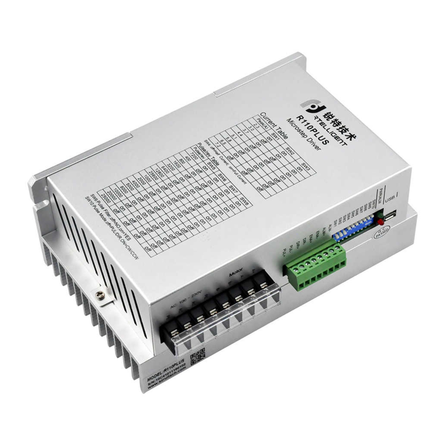
R110PLUS USER MANUAL 1. Product overview R110-PLUS is a high-voltage digital two-phase stepper motor driver with integrated intelligent motion controller functions and built-in S-shaped acceleration and deceleration commands. Through the USB port, it is convenient to configure the driver and expand the application of the driver. -
Page 4: Driver Installation Dimensions
R110PLUS USER MANUAL 2.2 Driver installation dimensions 3. Driver port and connection 3.1 Power and motor port function description Function Grade Definition Remarks Single-phase 220VAC Power supply power input connect two terminals of Reversing A+, A- or motor’s phase-B winding... -
Page 5: Control Signal Connection
R110PLUS USER MANUAL 3.2 Control signal connection Function Identification Description Pulse / IN1 PUL+ PUL- The control signal is 5~24V compatible. No Direction / DIR+ additional current DIR- limiting resistor is required. Enable /IN3 ENA+ ENA- Alarm /OUT1 ALM+ Optocoupler isolation,... -
Page 6: Alm (Out1) Port
R110PLUS USER MANUAL When the internal optocoupler is on, the driver will cut off the current of each phase of the motor to make the motor free, and the step pulse will not be responded. When the motor is in an error state, it is automatically turned off. The level logic of the enable signal can be set to the opposite. -
Page 7: The Setting Of Dip Switches And Operating Parameter
R110PLUS USER MANUAL 4. The setting of DIP switches and operating parameter The setting of current Standby current The setting of pulse per revolution Command filtering Pulse mode SW10 4.1 Current setting Remarks Sine peak A Users can set up 8 level currents through debugging software. -
Page 8: Pulse Command Filtering
R110PLUS USER MANUAL 1600 Users can set up 16 level subdivision 3200 through debugging software. 6400 12800 25600 1000 2000 4000 5000 8000 10000 20000 25000 4.4 Pulse command filtering The driver has a built-in pulse command smoothing function, which can make the motor start more stable. -
Page 9: Pulse Mode Setting
R110PLUS USER MANUAL 4.5 Pulse mode setting SW10 is used to set the form of the driver receiving pulse. SW10 = OFF, pulse + direction mode SW10 = ON, CW+CCW double pulse mode 5. Driver working status LED indication LED Status... -
Page 10: Communication Control Mode
R110PLUS USER MANUAL 7.1 Communication control mode In this mode, the user can make the motor run the specified pulse stroke or jog operation by communicating the given operation command. In internal pulse mode, the motor is controlled by register 18 0:Waiting state. -
Page 11: Jog Control Mode
7.1.2 Jog control mode R110Plus has the function of controlling the jog operation of the motor through communication.The specific modes and parameters to be set are as follows (register addresses are not specified or specified as decimal... -
Page 12: Io Control: Start And Stop + Direction
R110PLUS USER MANUAL Address Unit Parameter Description R/S^2 Acceleration of jog motion R/S^2 Deceleration of jog motion Speed of jog motion R/S^2 Emergency stop deceleration (4) Communication given operation command: Start jog movement by writing values 3 (continuous forward rotation) and 4 (continuous reverse rotation) to register 18.(For details on this register, please see "Drive Control Mode"... -
Page 13: Io Control: Forward + Reverse
R110PLUS USER MANUAL (3)IO settings: (4)This mode is for the speed defined by the speed table, selected by SW5, 6, 7, 8. (5)Set the motion parameters, you can modify the acceleration, deceleration 7.3 IO Control: Forward + Reverse Same as 7.2, only need to change (2) to: 3 – IO speed control: forward + reverse. -
Page 14: Common Faults And Troubleshooting
R110PLUS USER MANUAL 8. Common faults and troubleshooting Phenomenon Possible situations Solutions Check the power supply circuit for Power indicator is off normal power supply Pulse signal is weak; increase the The motor rotor is locked but the motor does not work... -
Page 15: Appendix A. Guarantee Clause
R110PLUS USER MANUAL Check power polarity or external short Short circuit between terminals circuit The driver terminal burned Check whether there is any solder ball Internal resistance between due to excessive addition of solder on terminals is too large the wire connections Appendix A.
Need help?
Do you have a question about the R110PLUS and is the answer not in the manual?
Questions and answers