
Related Manuals for Rtelligent R86


Summary of Contents for Rtelligent R86
- Page 1 R86 User Manual Digital Stepper Driver R86 User Manual Shenzhen Rtelligent Mechanical Electrical Technology Co.,ltd...
-
Page 2: Table Of Contents
R86 User Manual Contents 1.Product overview..........................1 2.Application environment and installation..................2 2.1Environmental requirement.....................2 2.2Driver installation dimensions....................2 2.3Driver installation requirements....................3 3.Driver Port and Connection......................3 3.1Port function description......................3 3.2Power supply input........................4 3.3Motor connection........................5 3.4Control signal connection......................5 3.4.1 PUL, DIR Port: connection for pulse command............5 3.4.2 ENA port: enable/disable....................6... -
Page 3: Product Overview
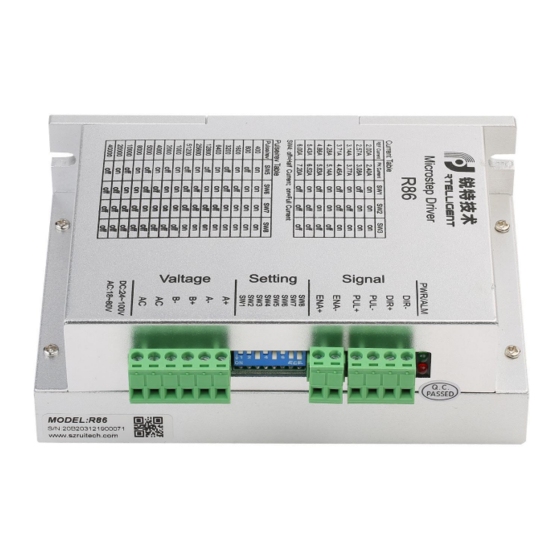
R86 driver can select the current and subdivision through the DIP switch. There are16 subdivisions and 8 current selections. It has over-voltage, under-voltage, and over-current protection. Its input and output control signals are optically isolated. -
Page 4: Application Environment And Installation
R86 User Manual 2. Application environment and installation 2.1 Environmental requirement Item Rtelligent R86 Installation environment Avoid dust, oil and corrosive environment Vibration 0.5G(4.9m/s2) Max 0℃ ~ 45℃ / 90% RH or less (no Operating temperature/humidity condensation) Storage and transportation -10℃... -
Page 5: Driver Installation Requirements
R86 User Manual 2.3 Driver installation requirements Please install the driver vertically or horizontally, with its front facing forward, top facing upward to facilitate cooling. During assembly, avoid drillings and other foreign matters falling inside the driver. During assembly, please use M3 screw to fix. -
Page 6: Power Supply Input
R86 User Manual 3.2 Power supply input The power supply of the driver can be both AC power and DC power, and the input voltage range is 20V~80VAC or 24V~100VDC. Please be minded that AC power cannot exceed 80VAC. and do not connect to commercial electricity(220VAC) directly! The driver’s work mode is constant current control. -
Page 7: Motor Connection
This is suitable for high speed required. 3.4 Control signal connection 3.4.1 PUL, DIR Port: connection for pulse command The signal interface of standard R series driver is in the form of pulse, and the R86 can receive two kinds of pulse command signals. -
Page 8: Ena Port: Enable/Disable
The upper controller can be the pulse signal generating device, such as PLC, MCU, control card and controller. The pulse level that R86 driver can be used: 3.3V-24V (no need to connect resistor) Pulse and direction (PUL + DIR) Reverse... -
Page 9: The Setting Of Dip Switches And Operating Parameters
R86 User Manual Common Cathode Pu l+ Pu l- Dir+ Driver Dir- Controller En a + En a - Difference Pul+ Pul+ Pul- Pul- Dir+ Dir+ Driver Dir- Dir- Controller Ena+ Ena+ Ena- Ena- 4. The setting of DIP switches and operating parameters... -
Page 10: The Setting Of Current
R86 User Manual 4.1 The setting of current Peak Current Average Current Remarks 2.4A 2.0A 3.1A 2.6A 3.8A 3.1A Other Current 4.5A 3.7A can be 5.2A 4.3A customiz 5.8A 4.9A 6.5A 5.4A 7.2A 6.0A DIP SW1, SW2, SW3 are used to set current which is output from driver to motor. -
Page 11: The Selection Of Half/Full Current
R86 User Manual 8000 10000 20000 40000 DIP SW5, SW6, SW7, and SW8 are used to set the pulse per revolution required by the motor. Motor speed = command pulse frequency ÷ pulse per revolution Motor stroke = number of command pulses ÷ pulse per revolution 4.3 The selection of Half/Full Current... -
Page 12: Common Faults And Troubleshooting
R86 User Manual 6. Common faults and troubleshooting Phenomenon Possible situations Solutions Check the power supply circuit for Power indicator is off normal power supply The motor rotor is locked but Pulse signal is weak; increase the the motor does not work... -
Page 13: Guarantee Clause
R86 User Manual Check whether there is any solder Internal resistance between ball due to excessive addition of terminals is too large solder on the wire connections Acceleration and deceleration Reduce command acceleration or time is too short increase Driver filtering parameters...
Need help?
Do you have a question about the R86 and is the answer not in the manual?
Questions and answers