Advertisement
I
NTRODUCTION
MCI-2 interface is a converter between RS485 (EPSO3) protocol and RACS
CLK/DTA protocol. The interface is used to connect MCT series terminal of
RACS 5 system to PR series controller of RACS 4 system or HRC series
controller of hotel automation system. Factory new device does not require low
level configuration and can be operated with default settings (RACS CLK/DTA
address ID0). Low level configuration of the MCI-2 interface with RogerVDM
requires RUD-1 interface.
C
R
ONFIGURATION WITH
OGER
Fig. 1 Connection of the MCI-2 to RUD-1 interface for configuration
Programming procedure with RogerVDM software:
1. Connect the device to RUD-1 interface (fig. 1) and connect the RUD-1 to
computer's USB port.
2. Remove jumper from MEM contacts (fig. 3) and restart the device (short RST
contacts for a moment or switch power supply off and on).
3. Within 5 seconds when orange LED SYSTEM indicator pulsates twice per
second, place jumper on MEM contacts and LED SYSTEM indicator will
pulsate quickly.
4. Start RogerVDM program, select MCI-2 v1.x device, v1.0 firmware version,
RS485 communication channel and serial port with RUD-1 interface.
5. Click Connect, the program will establish connection and will automatically
display Configuration tab.
6. If necessary, define address on RACS CLK/DTA bus and other settings
according to requirements of specific installation.
7. Click Send to Device to update the configuration.
8. Optionally make a backup by clicking Send to File... and saving settings to
file on disk.
9. Leave jumper on MEM contacts and disconnect device from RUD-1 interface.
F
IRMWARE UPDATE
The update requires connection of MCI-2 to computer with RUD-1 interface
(fig. 2) and starting RogerVDM software. The latest firmware file is available at
www.roger.pl.
Note: After firmware update it may be necessary to restore factory default
settings. Current configuration of device can be exported to file using RogerVDM
program before firmware update.
Firmware update procedure:
1. Connect the device to RUD-1 interface (fig. 2) and connect the RUD-1 to
computer's USB port.
2. Place jumper on FDM contacts (fig. 3).
3. Restart the device (short RST contacts for a moment or switch power supply
off and on).
4. Start RogerVDM program and in the top menu select Tools and then Update
firmware.
5. In the opened window select device type, serial port with RUD-1 interface
and path to firmware file (*.hex).
6. Click Update to start firmware upload with progress bar in the bottom.
7. When the update is finished, remove FDM jumper and restart the device.
8. If orange LED SYSTEM indicator slowly pulsates after restart then place
jumper on MEM contacts, wait 5 seconds and restart device to restore factory
default settings.
Roger Access Control System
MCI-2 Installation Manual
Firmware version: 1.0.30.265 and newer
Document version: Rev. A
VDM P
ROGRAM
Fig. 2 Connection of the MCI-2 to RUD-1 interface for firmware update
A
PPENDIX
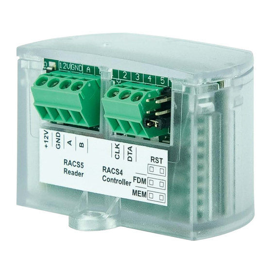
Fig. 3 MCI-2 interface
Table 1. MCI-2 screw terminals
Screw terminal
Description
+12V
12VDC power supply
GND
Ground
A
RS485 bus, line A
B
RS485 bus, line B
CLK
RACS CLK/DTA bus, line CLOCK
DTA
RACS CLK/DTA bus, line DATA
Table 2. MCI-2 indicators
Name
Colour
Description
LED
Orange
Pulsing: Configuration error
SYSTEM
Quick pulsing: Device in configuration mode
LED
Green
-
OPEN
LED
Red
Pulsing: Communication lost on RS485 (EPSO3) bus
STATUS
Green
Pulsing: Communication lost on RACS CLK/DTA bus
Table 3. Specification
Supply voltage
Nominal 12VDC, min./max. range 10-15VDC
Current
consumption
25mA
(average)
Distances
Up to 1200 m between interface and MCT reader
(RS485)
Up to 150m between interface and PR or HRC
controller (RACS CLK/DTA)
IP Code
IP20
Class I, indoor general conditions, temperature: +5°C
Environmental
class
to
+40°C,
(according
to
EN
50133-1)
condensation)
Dimensions W x S x G
36 x 55 x 47 mm
Weight
~16g
Certificates
CE
relative
humidity:
10
to
95%
(no
1/2
Advertisement
Table of Contents

Related Manuals for Roger MCI-2


Summary of Contents for Roger MCI-2
- Page 1 VDM P ONFIGURATION WITH OGER ROGRAM Fig. 2 Connection of the MCI-2 to RUD-1 interface for firmware update PPENDIX Fig. 1 Connection of the MCI-2 to RUD-1 interface for configuration Programming procedure with RogerVDM software: 1. Connect the device to RUD-1 interface (fig. 1) and connect the RUD-1 to computer’s USB port.
- Page 2 Fig. 4 Connection of MCI-2 interface to MCT reader and PR series controller Notes: If devices are not supplied from the same power supply then according to fig. 4 their GND terminals must be connected with any wire. MCT readers must be configured with default ID=100 address.
Need help?
Do you have a question about the MCI-2 and is the answer not in the manual?
Questions and answers