Roger PR611 Installation Manual
Access control system
Hide thumbs
Also See for PR611:
- Installation manual (13 pages) ,
- Function manual (43 pages) ,
- Installation manual (16 pages)
Table of Contents
Advertisement
Quick Links
Roger Access Control System
Installation guide for PR611, PR611-VP, PR621, PR311SE
and PR311SE-BK access controllers
Firmware version: x.18.6 or newer
Document version: Rev. L
© 2016 ROGER sp. z o.o. sp.k. All rights reserved. This document is subject to the Terms of Use in their current version published at
the
www.roger.pl
website of the Roger sp. z o.o. sp.k. company (hereinafter referred to as ROGER).
Advertisement
Table of Contents

Related Manuals for Roger PR611


Summary of Contents for Roger PR611
- Page 1 Firmware version: x.18.6 or newer Document version: Rev. L © 2016 ROGER sp. z o.o. sp.k. All rights reserved. This document is subject to the Terms of Use in their current version published at www.roger.pl website of the Roger sp. z o.o. sp.k. company (hereinafter referred to as ROGER).
-
Page 2: Table Of Contents
PR611 PR621 PR311SE Installation guide 2020-10-07 Contents 1. Introduction ........................3 2. Description and specification ..................3 3. Installation ........................4 3.1 Terminals/wires and connection diagram ................4 3.2 LED indicators ........................5 3.3 Power supply ........................6 3.4 Connection of door lock ...................... 6 3.5 Communication with controller .................... -
Page 3: Introduction
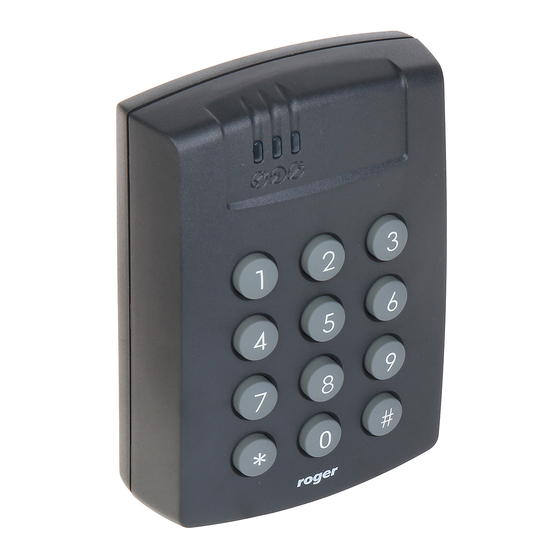
PR611, PR611-VP, PR621, PR311SE and PR311SE-BK are single door access controllers used in RACS 4 access control system. All devices are functionally identical but PR611, PR611-VP and PR311SE are equipped with keypad while PR621 and PR311SE-BK are not. Additionally, PR611-VP controller contrary to remaining ones is equipped with aluminium vandal-proof enclosure. -
Page 4: Installation
PR611 PR621 PR311SE Installation guide 2020-10-07 Dimensions HxWxD PR611/PR611-VP: 115 x 80 x 35 mm PR621: 85 x 85 x 27 mm PR311SE/PR311SE-BK: 152,5 x 46 x 23(35)mm Weight PR611/PR621: approx. 120g PR611-VP: approx. 470g PR311SE/PR311SE-BK: approx. 150g Certificates 3. I NSTALLATION 3.1 Terminals/wires and connection diagram... -
Page 5: Led Indicators
PR611 PR621 PR311SE Installation guide 2020-10-07 Fig. 1 Connection diagram 3.2 LED indicators Controllers are equipped with 3 LED indicators. Their functions and colours are specified in table 3 below. Functioning of LEDs can be verified by means of included MASTER card after connection of power supply to the controller. -
Page 6: Power Supply
PR611 PR621 PR311SE Installation guide 2020-10-07 Table 3. LED indicators Symbol Name Colour Description STATUS Red/Green Armed/Disarmed Mode respectively OPEN Green Door unlocking SYSTEM Orange Various system functions and programming 3.3 Power supply Controllers require 12VDC nominal power supply. The power should be connected to the +12V line and -12V line. -
Page 7: Communication Of Controller With Peripheral Devices
CLK/DTA. RACS CLK/DTA is the addressable bidirectional communication standard developed by Roger company. Addresses of all devices connected to CLK and DTA lines must be properly configured in range of 0..15. Factory default address of peripheral devices can be changed according to procedures specified in their manuals but in majority of cases it is not necessary to modify the addresses at all. -
Page 8: Wall Mounting
PR611 PR621 PR311SE Installation guide 2020-10-07 3.8 Wall mounting Fig. 3 Installation of PR611 controller 8/16... - Page 9 PR611 PR621 PR311SE Installation guide 2020-10-07 Fig. 4 Installation of PR621 controller 9/16...
- Page 10 PR611 PR621 PR311SE Installation guide 2020-10-07 Fig. 5 Installation of PR311SE controller (standard enclosure base) 10/16...
- Page 11 PR611 PR621 PR311SE Installation guide 2020-10-07 Fig. 6 Installation of PR311SE controller (additional enclosure base) 11/16...
-
Page 12: Installation Guidelines
PR611 PR621 PR311SE Installation guide 2020-10-07 3.9 Installation guidelines Install devices in such way as to ensure easy access to screw terminals and jumpers (RST, FDM) located inside the controller – see fig. 7. Prior to controller installation it is recommended to configure its address (ID number) – see 4.1 Controller address. -
Page 13: Addressing During Firmware Update (Fixed Id)
PR611 PR621 PR311SE Installation guide 2020-10-07 4.1.1 Addressing during firmware update (Fixed ID) FixedID can be set during update of the controller firmware by means of RogerISP software. Prior to firmware upload, RogerISP software offers the possibility to set Fixed ID address in range of 00..99 or disable it (FixedID=None). -
Page 14: Full Memory Reset Procedure
PR611 PR621 PR311SE Installation guide 2020-10-07 4.2.2 Full Memory Reset procedure Full Memory Reset restores default settings and enables programming of new MASTER card, MASTER PIN and controller ID address. In case of controller without keypad (PR621 and PR311SE- BK) it is necessary to connect PRT series reader with keypad (e.g. PRT12LT) to perform Full Memory Reset. -
Page 15: Firmware Update
2020-10-07 4.4 Firmware update The latest versions of firmware and Roger ISP software are available at www.roger.pl. In order to update firmware it is necessary to connect the device by means of RS485 bus to communication interface (UT-2USB or RUD-1) and then connect the interface to PC with installed Roger ISP software. -
Page 16: Product History
PR611 PR621 PR311SE Installation guide 2020-10-07 PR311SE-BK Access controller with built-in EM 125 kHz (UNIQUE) card reader PS-15DR 13.8VDC/1.5A power supply unit adapted to installation on DIN 35mm rail PS-20 13.8VDC/2A power supply unit in metal enclosure and space for 12V/7Ah backup...
Need help?
Do you have a question about the PR611 and is the answer not in the manual?
Questions and answers