Roger MCT82M-IO-HR Operating Manual
Hide thumbs
Also See for MCT82M-IO-HR:
- Operating manual (18 pages) ,
- Installation manual (2 pages) ,
- Installation manual (2 pages)

Related Manuals for Roger MCT82M-IO-HR


Summary of Contents for Roger MCT82M-IO-HR
- Page 1 Roger Access Control System MCT82M-IO-HR Operating Manual Product version: 1.0 Firmware version: 1.1.18 or newer Document version: Rev. D...
-
Page 2: Design And Application
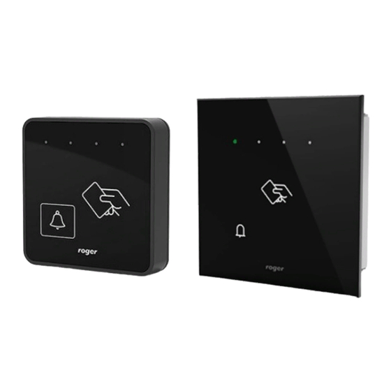
1. D ESIGN AND APPLICATION The MCT82M-IO-HR is an access terminal dedicated to RACS 5 system. The device enables identification of users by 13,56 MHz MIFARE® Ultralight/Classic/Plus/DESFire proximity cards. The terminal is mainly dedicated to hotel applications and besides room entry control it enables the presentation of such hotel signalizations with its LED indicators as Do Not Disturb, Make up the Room, Emergency Call and Service Call. - Page 3 MCT82M-IO-HR Operating Manual Rev. D.doc 22.06.2021 Fig. 1 MCT supply from MC16 access controller Fig. 2 MCT supply from dedicated power supply unit RS485 bus The communication with MC16 access controller is provided with RS485 bus which can encompass up to 16 devices of RACS 5 system, each with unique address in range of 100-115.
-
Page 4: Function Key
MCT82M-IO-HR Operating Manual Rev. D.doc 22.06.2021 Function key The terminal is equipped with touch function key. Various functions can be assigned to the key within high level configuration (VISO) e.g. door bell. LED indicators The terminal is equipped with four LED indicators which are mainly used to signal hotel functions but they can also be programmed with other available functions within high level configuration (VISO). - Page 5 MCT82M-IO-HR Operating Manual Rev. D.doc 22.06.2021 Table 3. Input types NO input NC input NO input can be in normal or in triggered state. In NC input can be in normal or in triggered state. In normal state C contacts are opened. Input normal state C contacts are closed.
-
Page 6: Tamper Detector
AN024 application note which is available at www.roger.pl. The technical characteristics of the device are guaranteed for RFID cards supplied by Roger. Cards from other sources may be used, but they are not covered by the manufactures warranty. Before deciding to use specific Roger products with third-party contactless cards, it is recommended to conduct tests that will confirm satisfactory operation with the specific Roger device and software in which it operates. - Page 7 Fig. 4 Internal side of the front panel Note: MCT82M-IO-HR enclosure consists of front panel and back panel. New device is assembled with a standard back panel, but additional free of charge, extended back panel is included. This panel can be used when connection cable has to be hidden and no flush mounting box is available.
- Page 8 MCT82M-IO-HR Operating Manual Rev. D.doc 22.06.2021 Fig. 5 MCT82M-IO-HR installation 8/17...
- Page 9 MCT82M-IO-HR Operating Manual Rev. D.doc 22.06.2021 Fig. 6 MCT82M-IO-HR-F installation 9/17...
-
Page 10: Operation Scenario
MCT82M-IO-HR Operating Manual Rev. D.doc 22.06.2021 Installation guidelines The terminal should be mounted on a vertical structure (wall) away from sources of heat and moisture. Front panel should be attached in such way as the tamper detector (fig. 4) would firmly press the back panel. -
Page 11: Low Level Configuration (Rogervdm)
MCT82M-IO-HR Operating Manual Rev. D.doc 22.06.2021 Low level configuration (RogerVDM) Programming procedure with RogerVDM software (firmware 1.1.30.266 or newer): 1. Connect the device to RUD-1 interface (fig. 8) and connect the RUD-1 to computer’s USB port. 2. Remove jumper from MEM contacts (fig. 4) if it is placed there. - Page 12 MCT82M-IO-HR Operating Manual Rev. D.doc 22.06.2021 Default value: 100. RS485 communication timeout [s] Parameter defines delay after which device will signal lost communication with controller by means of its LED indicators. When set to 0 then signaling is disabled. Range: 0-64s. Default value: 20s.
- Page 13 0-31 and 0-14 for sectors 32-39. Default value: 0. Key type Parameter defines key type used to access sector with PCN. Range: [0]: A, [1]: B, [2]: Roger. Default value: [0]: A. Parameter defines 6 bytes (12 HEX digits) key for accessing sector where PCN is stored.
-
Page 14: Manual Addressing
MCT82M-IO-HR Operating Manual Rev. D.doc 22.06.2021 Key type Parameter defines key type used to access sector with PCN. Range: [0]: A, [1]: B. Default value: [0]: A. Programmable card number (PCN) settings for Mifare Desfire Sector type Parameter defines sector type with programmable number (PCN). If the option [0]:None is selected then card returned number (RCN) will include only CSN and PCN will be discarded. -
Page 15: Memory Reset
MC16 access controller and it depends on applied scenario of operation. The example of access control system configuration is given in AN006 application note while hotel system configuration is explained in AN033 application note. Both notes are available at www.roger.pl. 5. F IRMWARE UPDATE The firmware of device can be changed to newer or older version. -
Page 16: Specification
MCT82M-IO-HR Operating Manual Rev. D.doc 22.06.2021 Fig. 9 Connection to RUD-1 interface (firmware update) 6. S PECIFICATION Table 6. Specification Supply voltage Nominal 12VDC, min./max. range 10-15VDC Current consumption ~60 mA (average) Inputs Three parametric inputs (IN1..IN3) internally connected to the power supply plus through a 5.6kΩ... - Page 17 Hotel room entry terminal; MIFARE Ultralight/Classic/Plus/DESFire reader; 4 programmable LEDs; door bell button; built-in IO lines; 12 V supply; glass front panel; QUADRUS series design; flush type enclosure RUD-1 Portable USB-RS485 communication interface dedicated to ROGER access control devices. 8. P RODUCT HISTORY Table 8.
Need help?
Do you have a question about the MCT82M-IO-HR and is the answer not in the manual?
Questions and answers