Table of Contents
Advertisement
Quick Links
Grass Collection Systems
System Number: Description:
5600001
2 Bag System - 44" Mower Deck
5600002
2 Bag System - 48" Mower Deck
5600003
3 Bag System - 48" Mower Deck
5600004
3 Bag System - 52" Mower Deck
5600007
3 Bag System - 52" Mower Deck
5600061
3 Bag System - 52" Mower Deck
5600148
3 Bag System - 52" Mower Deck
5600150
3 Bag System - 52" Mower Deck
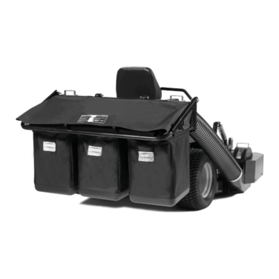
FAST-Vac
44", 48" & 52" Mower Decks
OPERATOR'S
MANUAL
with Setup Instructions
IMPORTANT NOTE:
These FAST-Vac Systems fit
2005 and newer Model Year
product equipped with the rubber
discharge chute.
Fits Models: Serial Number Range:
IS500Z
All
IS1500Z
IS1500Z
All
S50X
S150X
IS1500Z
All
S150X
IS1500Z
S/N: 2012628762 & Below
S150X
IS1000Z
S/N: 2531 & Above
IS2000Z
S/N: 2012628762 & Below
IS1500Z
S/N: 2012628763 & Above
S150X
IS2000Z
S/N: 2012628763 & Above
5103132
Rev: E
Advertisement
Table of Contents

Related Manuals for Ferris SNAPPER PRO FAST-Vac


Summary of Contents for Ferris SNAPPER PRO FAST-Vac
- Page 1 OPERATOR’S MANUAL with Setup Instructions FAST-Vac Grass Collection Systems 44”, 48” & 52” Mower Decks IMPORTANT NOTE: These FAST-Vac Systems fit 2005 and newer Model Year product equipped with the rubber discharge chute. System Number: Description: Fits Models: Serial Number Range: 5600001 2 Bag System - 44”...
- Page 2 General Information Thank you for purchasing this quality-built Ferris or Snapper Pro product. We’re pleased that you’ve placed your confidence in the Ferris or Snapper Pro brand. When operated and maintained according to the instructions in this manual, your Ferris or Snapper Pro product will provide many years of dependable service.
-
Page 3: Table Of Contents
TABLE OF CONTENTS SAFETY RULES & INFORMATION ....2 Safety Decals ............3 Safety Icons ............4 GENERAL OPERATING INSTRUCTIONS ..6 Before Operation .............6 Mowing with the Double / Triple Catcher ....6 After Operation ............7 Storing the Grass Catcher ........7 Mowing Without the Blower ........7 INSTALLATION ........... -
Page 4: Safety Rules & Information
Safety Rules & Information SAFETY RULES & INFORMATION Read these safety rules and follow them closely. Failure to obey these rules could result in loss of control of unit, severe personal injury or death to you, or bystanders, or damage to property or equipment. -
Page 5: Safety Decals
Safety Rules & Information Safety Decals Part Number: 7027733 - “Decal, Ear Protection” Before operating your unit, read the safety decals. The cautions and warnings are for your safety. To avoid a personal injury or damage to the unit, understand and follow all the safety decals. -
Page 6: Safety Icons
Safety Rules & Information 2-Bag & 3-Bag Collector Hood • Disengage the blower (blades) and remove the ignition key, wait for all parts to stop before disconnecting or unlatching any parts attached to blower or collection system. Warning - Read the Operator’s Manual. Caution - Always wear hearing protection when operating. - Page 7 Safety Rules & Information Danger - Thrown objects hazard: • Do not mow without discharge chute or entire grass catcher in place. Warning - Thrown objects hazard: • Do not open collection system container with engine running. • Do not operate with blower or collection system tube unlatched or missing.
-
Page 8: General Operating Instructions
General Operating Instructions GENERAL OPERATING INSTRUCTIONS Before Operation Clear the lawn of all sticks, stones, wire and other debris which may be caught or thrown by the mower blades. Check grass condition. If wet, wait until later in the day. If grass is wet, the grass catcher is likely to become plugged. -
Page 9: After Operation
General Operating Instructions After Operation Remove any debris from the the screen on the underside of the lid. Note: The lid screen can be partially removed for easier cleaning and should be cleaned regularly. The blower housing and tube should be removed for cleaning. -
Page 10: Installation
6. Remove the jack from under the suspension cross member. 7. Remove the jackstands from under the machine. For All Other Ferris Models: WARNING 3. Remove the rear drive tires. Use two hands when adjusting the shock 4. See Figure 1. Using the supplied spanner wrench (p/n 5022853), insert the tip of the wrench springs. -
Page 11: Ball Joint Hardware Replacement
Installation Ball Joint Hardware Replacement (Ferris IS2000Z & IS2500Z Models with 52” Mower Decks Only) The hardware and spacers that secure the rear ball joint (A, Figure 2) on the right hand front suspension arm has to be replaced with the hardware and spacer included with this kit. -
Page 12: Prepare Discharge Chute Opening
Installation Prepare Discharge Chute Opening Remove the Discharge Chute & Deck Guard 1. Remove the discharge chute (A, Figure 4), chute mount rod (B) and mounting hardware. NOTE: Retain the discharge chute, chute mount rod, and mounting hardware. If the blower is removed from the unit they need to be reinstalled for safe operation. -
Page 13: Preparing The Blower Mount For Assembly
Installation Preparing the Blower Mount for Assembly Inspecting the Blower Mount Assembly Some blower mounts are equipped with an adjustable deflector bracket (A, Figure 6). If your blower mount is equipped with an adjustable deflector bracket it will need to be adjusted prior to performing the Blower Assembly procedure. -
Page 14: Blower Assembly
Installation Blower Assembly 1. Remove the existing 5/16-18 x 5/8” flange head bolts (B, Figure 9) from the blower housing (A). 2. Install the blower mount plate (C) onto the blower housing and reinstall the 5/16-18 x 5/8” flange head bolts. Tighten securely. 3. - Page 15 Installation 5. Remove the blower belt guard and set aside. 6. Install the impeller drive pulley (A, Figure 11) onto Hub pointing OUT: the impeller shaft (B) as described in Figure 11. Hub pointing IN: 52” Models Install the 1/4” x 1-1/2” long key (not shown) in the 44”...
-
Page 16: Mower Deck Preparation
Installation Mower Deck Preparation Remove the Spindle Belt Identify and follow the correct procedure for your unit. WARNING IS500Z, 1000Z, IS1500Z, IS2000Z, S50X, & S150X Models: Use extreme caution when rotating the idler arm with the breaker bar, due to the increased tension in the spring as the idler arm is being rotated. - Page 17 Installation Remove the Spindle Pulley 1. Remove the 3/4-16 hex nut & 3/4” spring washer (A & B, Figure 16) securing the spindle pulley (C) to the spindle shaft. Use a 1” wrench on the flats of the blade end of the spindle shaft to prevent the shaft from spinning.
-
Page 18: Blower Installation
Installation Reinstall the Spindle Belt Refer to “Remove the Spindle Belt” on page 14 and reverse the order for reinstalling the belt. Install the Deck Guard 1. Install the new deck guard onto the mower deck and secure with the hardware previously removed (see Figure 18). - Page 19 Installation 2. Install the blower drive belt. Refer to Figure 21 for the proper belt routing. It may be required to loosen the idler pulley mounting hardware to get the belt past the belt keeps. IMPORTANT NOTE: The gray area denotes the flat side of the belt.
-
Page 20: Collector Installation
Installation Collector Installation Install Collector Mount Plate Identify and follow the correct procedure for your unit. (1000Z & IS1000Z Series) 1. Remove the hardware securing the rear bumper screen (A, Figure 24) to the top and bottom bumpers (A, B). Save the 3/8” bolts and washers from the lower bumper. - Page 21 Installation (IS500Z Series, IS1500Z Series, & IS2000Z Series) 1. Install the collector mount plate (A, Figure 26) and mount tabs (B) on to the bumper. Install two of the 3/8-16 U-bolts (C) over the top bumper tube and through the mount tabs and loosely secure with the 3/8-16 nylock flange nuts (F).
- Page 22 Installation (S50X & S150X Series) 1. Remove the carb. shield plate from top of the rear bumper. 2. Install the collector mount plate (A, Figure 28) and mount tabs (B) on to the bumper. Install the 3/8-16 x 1-1/4” bolts (C) and 3/8” SAE washers (F) through the mount tabs and loosely secure with the 3/8-16 nylock flange nuts (E).
- Page 23 Installation Assemble Collector Hood 1. Install the inlet tube (B, Figure 30) to the collector 3. Install the collector onto the mount plate and back plate (A) and secure with the 5/16-18 x 3/4” secure with the hitch pins as shown in Figure 30. bolts (C) and 5/16-18 nylock flange nuts (D).
- Page 24 Installation Install Collector Bags 1. Raise the collector hood and slide the collector bags (A, Figure 31) onto the frame rails (B). NOTE: The collector bags are constructed with three mesh panels and one solid panel. Install the bag with the solid panel towards the front of the machine.
- Page 25 Installation Install Hose 1. Lower the mower deck to the lowest cutting position. 2. Install the hose (A, Figure 33) onto the blower and secure with the removable clamp (with knob) (B). At least two bands must cover the outlet of the blower (C).
-
Page 26: Weight Mount Installation
Installation Weight Mount Installation Install Weight Carrier (1000Z Series) 1. Remove the hairpin clip and clevis pin and remove the deck lift foot pedal. Lift the floor plate. 2. Install the weight carrier (E, Figure 34), mount plates (B & C) and fasten with the 3/8-16 x 3” bolts (A) and 3/8-16 nylon lock nuts (D). - Page 27 Installation (IS1000Z Series) 1. Install the left-hand and right-hand weight carriers (E & H, Figure 35), bar clamps (F) and fasten with the 5/16-18 x 2-1/2” bolts (B) and 5/16-18 nylon lock nuts (G). Make sure carriers are tight against the outside of the suspension arm and do not interfere with the shock/spring assembly.
- Page 28 Installation (IS500Z & IS1500Z Series) (S50X & S150X Series) 1. Install the weight carrier (A, Figure 36) onto the front of the unit and secure with the 1/2-20 x 1-1/4” bolts (B), 1/2” washers (C) and 1/2-20 nylon lock nuts (D). 2.
-
Page 29: Blower & Collector Removal
Blower & Collector Removal BLOWER & COLLECTOR REMOVAL 1. Remove the knobs (A, Figure 38) securing the deck guard top (B) to the deck guard. 2. Pull the blower idler arm lever (C) forward to release the belt tension and remove the belt from the spindle pulley. -
Page 30: Maintenance
Maintenance MAINTENANCE Maintenance Schedule Before Each Use Check the blower housing and impeller. Check condition of collection bags. Clean muffler and rear frame area. Clear rear screen in hood (equipped models only) Every 25 Hours Lubricate the machine. Every 50 Hours Check the condition of the blower drive belt Check the Blower Housing and Impeller 1. -
Page 31: Unplugging A Clogged Unit
Maintenance If the blower is plugged: Unplugging a Clogged Unit 1. Park the machine on a flat, level surface. Conditions such as grass that is too long or too wet or Disengage the PTO, engage the parking brake, cutting at too fast of a ground speed could cause the turn off the ignition and remove the ignition key. -
Page 32: Troubleshooting
Troubleshooting TROUBLESHOOTING WARNING Troubleshooting Chart To avoid serious injury, perform maintenance on the tractor or mower only when the engine is While normal care and regular maintenance will stopped and the parking brake engaged. extend the life of your equipment, prolonged or Always remove the ignition key, disconnect constant use may eventually require that service be the spark plug wire and fasten it away from... - Page 33 Notes...
- Page 34 Notes...
- Page 36 OPERATOR’S MANUAL with Setup Instructions FAST-Vac Grass Collection Systems 44”, 48” & 52” Mower Decks Briggs & Stratton Power Products Group, LLC. 5375 North Main Street Munnsville, NY 13409 800-933-6175 www.ferrismowers.com www.snapperpro.com...
Need help?
Do you have a question about the SNAPPER PRO FAST-Vac and is the answer not in the manual?
Questions and answers