Table of Contents
Advertisement
This manual is available in Spanish. For a copy, contact your Ferris dealer or www.ferrisindustries.com.
Este manual está disponible en Español. Para obtener una copia, póngase en contacto con su
Model Number: Description
Powerhead
5900631
H2225KAV
5900651
H2226B
5900701
H2227KOH
5900933
H2226KAV
5900956
H2227B
5900533
H2224KAVFS 3-Wheel Rider
5900534
H2228B
Mower Deck
5900632
R61
distribuidor Ferris o www.ferrisindustries.com.
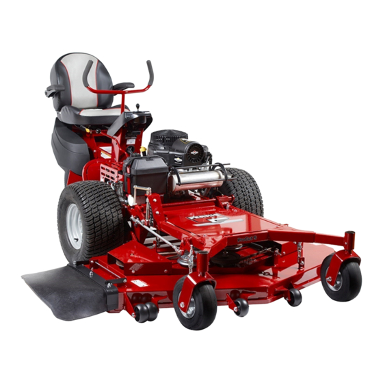
OPERATOR'S
MANUAL
ProCut S Series
3-Wheel Riding Mowers
3-Wheel Rider
3-Wheel Rider
3-Wheel Rider
3-Wheel Rider
3-Wheel Rider
3-Wheel Rider
61" Mower Deck
5100699
Rev: N
Advertisement
Table of Contents
Troubleshooting

Subscribe to Our Youtube Channel
Related Manuals for Ferris ProCut S Series


Summary of Contents for Ferris ProCut S Series
- Page 1 Mower Deck 5900632 61” Mower Deck This manual is available in Spanish. For a copy, contact your Ferris dealer or www.ferrisindustries.com. Este manual está disponible en Español. Para obtener una copia, póngase en contacto con su distribuidor Ferris o www.ferrisindustries.com.
- Page 2 Thank you for purchasing this quality-built FERRIS product. We’re pleased that you’ve placed your confidence in the FERRIS brand. When operated and maintained according to the instructions in this manual, your FERRIS product will provide many years of dependable service.
-
Page 3: Table Of Contents
Table of Contents Operator Safety ..........2 Identification Numbers ..........8 Safety Decals ............9 Safety Interlock System ........10 Features & Controls ......... 11 Control Functions ..........11 Operation ............13 General ..............13 Checks Before Starting .........13 Starting the Engine ..........14 Stopping the Rider ..........14 Three Wheel Rider Driving Practice .....15 Mowing ..............16 Mowing Recommendations ........16... -
Page 4: Operator Safety
Operator Safety Operating Safety Congratulations on purchasing a superior-quality piece of lawn and garden equipment. Our products are designed and manufactured to meet or exceed all industry standards for safety. Do not operate this machine unless you have been trained. Reading and understanding this operator’s manual is a way to train yourself. -
Page 5: Slope Operation
Operator Safety Slope Operation Operation on slopes can be dangerous. Using the unit on a slope that is too steep where you do not have adequate wheel traction (and control) can cause sliding, loss of steering, control, and possible rollover. You should not operate on a slope greater than a 5.4 foot rise over a 20 foot length (15 degrees). - Page 6 Operator Safety Retaining Walls, Drop-offs, and Water Retaining walls and drop-offs around steps and water are a common hazard. Give yourself a minimum of two mower widths of clearance around these hazards and hand-trim with a walk behind mower or string trimmer. Wheels dropping over retaining walls, edges, ditches, embankments, or into water can cause rollovers, which may result in serious injury, death, or drowning.
- Page 7 Operator Safety Read these safety rules and follow them closely. Failure to obey these rules could result in loss of control of unit, severe personal injury or death to you, or bystanders, or damage to property or equipment. This mowing deck is capable of amputating hands and feet and throwing objects. The triangle in text signifies important cautions or warnings which must be followed.
- Page 8 Operator Safety 23. Use care when approaching blind corners, shrubs, Do Not trees or other objects that may obscure vision. 1. Avoid starting, stopping, or turning on a slope. 24. To reduce fire hazard, keep unit free of grass, If tires lose traction (i.e. machine stops forward leaves &...
- Page 9 Operator Safety SERVICE AND MAINTENANCE mufflers, and engine to prevent fires. Clean up oil or fuel spillage. To avoid personal injury or property damage, use 10. Let engine cool before storing and do not store extreme care in handling gasoline. Gasoline is near flame.
-
Page 10: Identification Numbers
Operator Safety Identification Numbers North American Models Figure. 1 Location of Identification Tags. A. Powerhead Identification Tag B. Mower Deck Identification Tag www.ferrisindustries.com... -
Page 11: Safety Decals
Operator Safety SAFETY DECALS Before operating your unit, read the safety decals. The cautions and warnings are for your safety. To avoid a personal injury or damage to the unit, understand and follow all safety decals. WARNING If any safety decals become worn or damaged, and cannot be read, order replacement decals from your local dealer. -
Page 12: Safety Interlock System
Operator Safety Safety Icons SAFETY The alert symbol is used to identity safety information about hazards that can result in personal INTERLOCK SYSTEM injury. A signal word (DANGER, WARNING, or CAUTION) is used with the alert symbol to indicate the likelihood and the potential severity of the injury. This unit is equipped with safety interlock switches In addition, a hazard icon may be used to represent and other safety devices. -
Page 13: Features & Controls
Features and Controls Figure 2. Control Locations CONTROL FUNCTIONS The information below briefly describes the function of individual controls. Starting, stopping, driving, and mowing require the combined use of several controls applied in specific sequences. To learn what combination and sequence of controls to use for various tasks see the OPERATION section. Ground Speed Pedal Parking Brake This pedal controls the ground speed of the... -
Page 14: Features And Controls
Features and Controls PTO (Power Take Off) Switch Steering Handles Turn the handle in the desired direction to turn the The PTO switch engages and disengages the mower. machine. The farther the handle is turned, the tighter Pull UP on the switch to engage, and push DOWN to the turn will be disengage. -
Page 15: Operation
Operation GENERAL OPERATING SAFETY CHECKS BEFORE STARTING Before first time operation: • Check that crankcase is filled to full mark on dipstick. See the engine Operator’s Manual for • Be sure to read all information in the Safety and instructions and oil recommendations. Operation sections before attempting to operate this tractor and mower. -
Page 16: Starting The Engine
Operation WARNING If you do not understand how a specific control functions, or have not yet thoroughly read the FEATURES & CONTROLS section, do so now. Do NOT attempt to operate the tractor without first becoming familiar with the location and function of ALL controls. -
Page 17: Three Wheel Rider Driving Practice
Operation THREE WHEEL RIDER DRIVING Driving the Mower PRACTICE 1. Sit on the seat and adjust the seat so that you can comfortably reach all the controls and see the The speed and steering controls of the Three Wheel dash panel. rider are responsive, and learning to gain a smooth and efficient control of the rider’s forward, reverse, 2. -
Page 18: Mowing
9. Stop the engine (see STOPPING THE ENGINE & MOWER) MOWING RECOMMENDATIONS Several factors can affect how well your machine cuts grass, Ferris recommends following proper mowing recommendations to improve the performance and life of your machine. Height of Grass... -
Page 19: Mowing Methods
Operation When and How Often to Mow The time of day and condition of the grass greatly affect the results you’ll get when mowing. For the best results, follow these guidelines: 1. Mow when the grass is between three and five inches high. -
Page 20: Pushing The Rider By Hand
Operation Proper Mulching PUSHING THE RIDER BY HAND Mulching consists of a mower deck which cuts and DO NOT TOW RIDER recuts clippings into tiny particles and which then Towing the unit will cause hydraulic pump blows them down INTO the lawn. These tiny particles and wheel motor damage. -
Page 21: Storage
Operation STORAGE WARNING Temporary Storage (30 Days Or Less) Never store the unit, with gasoline in engine or fuel tank, in a heated shelter or in enclosed, Remember, the fuel tank will still contain some poorly ventilated enclosures. Gasoline fumes gasoline, so never store the unit indoors or in any may reach an open flame, spark or pilot light other area where fuel vapor could travel to any... -
Page 22: Regular Maintenance
Regular Maintenance MAINTENANCE SCHEDULE & PROCEDURES The following schedule should be followed for normal care of your mower. You will need to keep a record of your operating time. UNIT MAINTENANCE ENGINE MAINTENANCE Before Each Use Before Each Use Check Safety Interlock System Check Engine Oil Level Check Rider Brakes Every 25 Hours... -
Page 23: Checking Tire Pressures
Regular Maintenance CHECK TIRE PRESSURES Tire pressure should be checked periodically, and maintained at the levels shown in the chart. Note that these pressures may differ slightly from the “Max Inflation” stamped on the side-wall of the tires. The pressures shown provide proper traction, improve cut quality, and extend tire life. -
Page 24: Check Hydraulic Oil Level
Regular Maintenance CHECK HYDRAULIC OIL LEVEL 1. Observe the oil reservoir (A, Figure 7). The oil level should be at the “FULL” line (C). 2. Before removing the reservoir cap, make sure the area around the reservoir cap is free of dust, dirt, or other debris. -
Page 25: Lubrication
Use grease fittings when present. Disassemble parts to apply grease to moving parts when grease fittings are not installed. Not all greases are compatible. Ferris Red Grease (p/n 5022285) is recommended, automotive-type high-temperature, lithium grease may be used when this is not available. -
Page 26: Battery Maintenance
Regular Maintenance Lubricating the Front Casters Interval: Annually 1. Remove the 1/4-28 bolt (A, Figure 10) that is screwed into the caster and install a 1/4-28 grease fitting. 2. Grease the front caster. 3. Remove the 1/4-28 grease fitting and reinstall the 1/4-28 bolt. -
Page 27: Servicing The Mower Blades
Regular Maintenance SERVICING THE MOWER BLADES Removing the Mower Blade CAUTION Avoid injury! Mower blades are sharp. • Always wear gloves when handling mower blades or working near blades. 1. See Figure 12. To remove the mower blade, wedge a wooden block between the mower blade and the mower deck housing to keep the mower blade from turning, then remove the mower blade and the blade retaining hardware. - Page 28 Troubleshooting, Adjustment & Service Sharpening the Mower Blade CAUTION Avoid injury! Mower blades are sharp. • Always wear gloves when handling the mower blades. • Always wear safety eye protection when grinding. Figure 15. Sharpening the Mower Blade 1. Sharpen the mower blades with grinder, hand file, A.
-
Page 29: Troubleshooting, Adjustments & Service
Troubleshooting, Adjustment & Service TROUBLESHOOTING WARNING While normal care and regular maintenance will To avoid serious injury, perform maintenance extend the life of your equipment, prolonged or on the mower only when the engine is stopped constant use may eventually require that service be and the parking brake engaged. -
Page 30: Troubleshooting The Mower
Troubleshooting, Adjustment & Service Rider Troubleshooting Continued. PROBLEM CAUSE REMEDY Engine runs, but mower will not Hydraulic release valves in “open” Position hydraulic release valves in drive. position. “drive” position. Belt is broken. See Drive Belt Replacement. Drive belt slips. See problem and cause below. -
Page 31: Troubleshooting Common Cutting Problems
Troubleshooting, Adjustment & Service TROUBLESHOOTING COMMON CUTTING PROBLEMS PROBLEM CAUSE REMEDY Streaking 1. Sharpen your blades. 1. Blades are not sharp. 2. Replace your blades. 2. Blades are worn down too far. 3. Always mow at FULL throttle. 3. Engine speed is too slow. 4. -
Page 32: Mowing Height Adjustment
Troubleshooting, Adjustment & Service MOWING HEIGHT ADJUSTMENT See Figure 18. The mowing height adjustment can be changed by turning the cutting height adjustment handle. To Raise the Mower Deck: Turn the cutting height adjustment handle (A, Figure 18) CLOCKWISE. To Lower the Mower Deck: Turn the cutting height adjustment handle COUNTER- CLOCKWISE. -
Page 33: Mower Belt Replacement
Troubleshooting, Adjustment & Service MOWER BELT REPLACEMENT To avoid damaging belts, DO NOT PRY BELTS OVER PULLEYS. Mower Deck Drive Belt 1. Park the machine on a smooth, level surface such as a concrete floor. Disengage the PTO, engage the parking brake, turn off the engine, and remove the ignition key. -
Page 34: Transmission Drive Belt Replacement
Troubleshooting, Adjustment & Service 3. Measure the coil length of the mower belt tension spring (A, Figure 22). The measurement should equal 6-1/4” (15,9). If the measurement doesn’t equal 6-1/4” (15,9), adjust the mower belt idler tensioner spring length. Adjusting the Mower Belt Idler Tensioner Spring Length (S/N: 2015249869 &... -
Page 35: Deck Lift Rod Timing Adjustment
Troubleshooting, Adjustment & Service DECK LIFT ROD TIMING ADJUSTMENT 1. Park machine on a flat, level surface. Disengage the PTO, stop the engine, and engage the parking brake. Make sure that all of the tires are properly inflated. 2. Place a level (A, Figure 24) on top of the cutting height indicator (E) and adjust the cutting height indicator up or down with the deck height adjustment handle (B) until the cutting height... -
Page 36: Deck Leveling Adjustment
Troubleshooting, Adjustment & Service DECK LEVELING ADJUSTMENT NOTE: Before adjusting the deck level, the deck lift rod timing must be checked and if necessary, adjusted. 1. Park machine on a flat, level surface. Disengage the PTO, stop the engine, engage the parking brake, and remove the key from the ignition. -
Page 37: Transmission Foot Control Pedal Neutral Adjustment
Troubleshooting, Adjustment & Service TRANSMISSION FOOT CONTROL PEDAL NEUTRAL ADJUSTMENT If the tractor “creeps” (gradually moves forward or 4. Refer to 30. Make sure that the top plastic backwards) while the transmission foot control pedal bushing (E) is seated tightly against the top of the is in the neutral position, then it may be necessary neutral return bracket (G). -
Page 38: Parking Brake Adjustment
Repeat process for other side. 5. Re-engage the parking brake handle and unchock the wheels. If this does not correct the braking problem, see Figure 31. Parking Brake Adjustment you Ferris dealer. A. Parking Brake Spring B. Set Collar www.ferrisindustries.com... -
Page 39: Rear Suspension Adjustment
Troubleshooting, Adjustment & Service REAR SUSPENSION ADJUSTMENT POSITION #1 POSITION #2 (FACTORY SET) The shock assembly can be adjusted in two ways to allow the operator to customize the ride according to operator’s weight and/or operating conditions. You have the option of adjusting the spring pre-load and/ or the upper mounting position. -
Page 40: Battery Service
Troubleshooting, Adjustment & Service The best method of making certain a battery is BATTERY SERVICE fully charged, but not over charged, is to measure the specific gravity of a cell once per hour. The WARNING battery is fully charged when the cells are gassing Keep open flames and sparks away from the freely at low charging rate and less than 0.003 change in specific gravity occurs over a three hour... - Page 41 Troubleshooting, Adjustment & Service THIS HOOK-UP FOR NEGATIVE GROUND VEHICLES Starter Starter Switch Switch Jumper Cable Starting Discharged Vehicle Vehicle Battery Battery Jumper Cable To Ground Engine Block MAKE CERTAIN VEHICLES DO NOT TOUCH Figure 33. Jump Starting WARNING WARNING Any procedure other than the preceding could For your personal safety, use extreme care result in:...
-
Page 42: Specifications
Specifications †Power Ratings: All power levels are stated gross horsepower per SPECIFICATIONS SAE J2723 as rated by Kawasaki and tested per the SAE J1995 NOTE: Specifications are correct at time of printing and are subject test standard. The gross power curves and more information can be to change without notice. - Page 43 Ferris dealer during the warranty period. Ferris’ obligation under this limited warranty is, at Ferris’ option, to repair or replace any part or parts of the mower, which, in the judgment of Ferris, are found to be defective and covered by this limited warranty.
- Page 44 OPERATOR’S MANUAL ProCut S Series 3-Wheel Riding Mowers Briggs & Stratton Power Products Group, LLC. 5375 North Main Street Munnsville, NY 13409 800-933-6175 www.ferrisindustries.com...
Need help?
Do you have a question about the ProCut S Series and is the answer not in the manual?
Questions and answers
With the Procut S, is there anyway to view how much fuel is in the fuel tank? When you fill the gas tank does it fill both the left and right tanks simultaneously?
To check the fuel level in the Ferris ProCut S, use the fuel level gauge located in the tank. When filling the gas tank, fill it to the bottom of the filler neck to allow for fuel expansion. The information provided does not specify if there are separate left and right tanks or if filling one tank fills both, so that cannot be determined.
This answer is automatically generated
Do I need to remove the mower deck to replace the drive belt