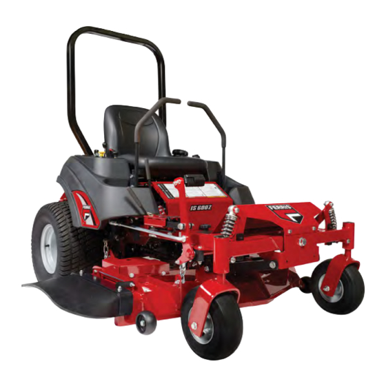
Ferris IS600z series Operator's Manual
Zero-turn
Hide thumbs
Also See for IS600z series:
- Operator's manual (32 pages) ,
- Operator's manual (44 pages) ,
- Operator's manual (52 pages)
Table of Contents
Advertisement
Advertisement
Table of Contents
Troubleshooting

Subscribe to Our Youtube Channel
Related Manuals for Ferris IS600z series


Summary of Contents for Ferris IS600z series
-
Page 2: Table Of Contents
Neutral Lockout Adjustment..........29 Table of Contents: Parking Brake Adjustment..........29 Products Covered by This Manual........3 Deck Lift Rod Timing Adjustment ........30 Identification Tag Location...........3 Deck Leveling Adjustment..........31 Product Identification Tag (Stamped).........3 Mower Deck Drive Belt Replacement......32 Operator Safety..............3 Transmission Drive Belt Replacement......32 Safety Decals..............10 Rear Suspension Adjustment.........33 Safety Icons..............11... -
Page 3: Products Covered By This Manual
All rights reserved. When contacting your authorized dealer for replacement parts, Ferris is a trademark of Briggs & Stratton Power Products Group, service, or information you MUST have these numbers. The Illustrated Parts List for this machine can be downloaded from ferrismowers.com. - Page 4 Operating Safety Children Congratulations on purchasing a superior-quality piece of lawn Tragic accidents can occur with children. Do not allow them and garden equipment. Our products are designed and anywhere near the area of operation. Children are often attracted manufactured to meet or exceed all industry standards for safety. to the unit and mowing activity.
- Page 5 Thrown Objects Keep the roll bar in position and fasten the seat belt. Do not jump off if the mower tips (it is safer to be secured by the seat belt.) NEVER remove the roll bar. Retaining Walls, Drop-Offs and Water This unit has spinning mower blades.
- Page 6 Gasoline should be stored only in sealed containers approved • Use extra care when handling gasoline and other fuels. for fuel. They are flammable and vapors are explosive. • Use only an approved container. Proper maintenance is critical to the safety and performance of •...
- Page 7 • Never carry passengers and keep pets and bystanders • Mow across slopes, not up and down. away. • Remove obstacles such as rocks, tree limbs, etc. • Do not operate the unit while under the influence of alcohol • Watch for holes, ruts, or bumps. Uneven terrain could or drugs.
- Page 8 • Before and during reverse operation, look behind and down • Always observe safe refueling and fuel handling practices for small children. when refueling the unit after transportation or storage. • Never carry children, even with the blade(s) off. They may •...
- Page 9 • Only authorized service locations should be utilized for To maintain operator roll over protection and roll bar major service and repair requirements. effectiveness: • Never attempt to make major repairs on this unit unless you • If a ROLL BAR becomes damaged for any reason, such as have been properly trained.
-
Page 10: Safety Decals
• The seat belt like the ROLL BAR, needs to be periodically inspected to verify that the integrity has not been compromised through normal machine use, misuse, age degradation, modifications, or a roll over. If the seat belt does not pass all of the following tests, it should be replaced. •... -
Page 11: Safety Icons
Callout Description Rollover Hazard Tipover Keep ROPS in Raised Position Keep Children Away Slippery Slopes Part Number: 5100683 - Decal, Safety Alert Symbol and Signal Words Warning, ROPS Removed The safety alert symbol is used to identify safety information about hazards that can result in personal injury. A signal word (DANGER, WARNING, or CAUTION) is used with the alert symbol to indicate the likelihood and the potential severity of injury. -
Page 12: Features And Controls
Engage Locks the parking brake. WARNING If the unit does not pass a safety test, do not operate it. See your authorized dealer. Under no circumstance should you Ground Speed Control Levers: These levers control the attempt to defeat the purpose of safety interlock system. ground speed and direction of the rider. -
Page 13: Instrument Control Panel
Retractable Seat Belt: The seat belt is used to secure the operator to the seat. Choke: Close the choke for cold starting. Open the choke once the engine starts. A warm engine may not require choking. The seat belt should always be worn when using this equipment Pull the knob UP to close the choke. -
Page 14: Checks Before Starting
Starting the Engine WARNING WARNING • Never operate on slopes greater than 15°. • Select slow ground speed before driving onto a slope. • If you do not understand how a specific control functions, Use extra caution when operating on slopes with a or have not yet thoroughly read the Features &... - Page 15 this practice session (ALWAYS operate at full throttle when mowing), and turn slowly to prevent tire slippage and damage to your lawn. We suggest you begin with the Smooth Travel procedure to the right, and then advance through the forward, reverse, and turning maneuvers.
-
Page 16: Mowing
Your Zero Turn Rider’s unique ability to turn in place allows you While traveling forward allow one handle to gradually return to turn around at the end of a cutting row rather than having to back toward neutral. Repeat several times. stop and Y-turn before starting a new row. -
Page 17: Mowing Recommendations
Mowing Recommendations Several factors can affect how well your machine cuts grass, Following proper mowing recommendations can improve the performance and life of your machine. Height of Grass Often cutting height is a matter of personal preference. Typically, you should mow the grass when it is between three and five inches high. -
Page 18: Pushing The Rider By Hand
Mulching consists of a mower deck which cuts and re-cuts clippings into tiny particles and which then blows them down INTO the lawn. These tiny particles decompose rapidly into by-products your lawn can use. UNDER PROPER CONDITIONS, your mulching mower will virtually eliminate noticeable clippings on the lawn surface. -
Page 19: Attaching A Trailer
Excessive towed loads can cause loss of traction and loss of control on slopes. Reduce towed weight when operating on 3. To open the transmission bypass valve (bypass position) slopes. The surface being driven on greatly impacts traction (C), move the transmission release lever up and pull it and stability. -
Page 20: Maintenance Schedule
• If the unit can’t be stored on a reasonable level surface, 5. See engine owner’s manual and follow all instructions for chock the wheels. preparing engine after storage. • Clean all grass and dirt from the mower. 6. Check crankcase oil level and add proper oil if necessary. If any condensation has developed during storage, drain Long Term Storage (Longer Than 30 Days) crankcase oil and refill. -
Page 21: Maintenance Procedures
4. If your unit is equipped with two fuel tanks, repeat this Maintenance Procedures process to fill the other fuel tank. Service and Maintenance Safety NOTICE Refer to your engine owner's manual for specific fuel WARNING recommendations. Amputation and crushing hazard Specific steps must be taken in order to perform service and Replacing the Fuel Filter maintenance procedures safely. -
Page 22: Engine Maintenance
WARNING Replacement parts must be the same and installed in the same position as the original parts or fire could result. Fuse Location and Identification The electrical system for this unit is equipped with two replaceable fuses. See the chart below for the circuit, amperage, and approximate location of the fuses. -
Page 23: Transmission Oil Filter Change
Transmission Oil Filter Change Purging the Air from the Hydraulic System Change Interval: Every 400 Hours or Yearly (Initial hydraulic Due to the effects air has on efficiency in hydraulic drive oil and filter change after first 100 hours of operation) systems, it is critical that it be purged from the system. -
Page 24: Lubricate The Front Casters
Use grease fittings when present. Disassemble parts to apply grease to moving parts when grease fittings are not installed. Not all greases are compatible. Red grease (p/n 5022285) is recommended. Automotive type, high temperature, lithium grease may be used when this is not available. Control handle pivots &... - Page 25 2. Using a wrench, remove the bolt securing the blade to the spindle. 3. If the cutting edges are not sharp or have nicks, sharpen the blades. See Sharpening the Mower Blades. Inspecting the Mower Blades Sharpening the Mower Blades DANGER Thrown objects hazard WARNING...
-
Page 26: Seat Adjustment
4. The mower blade should have a maximum of 1/64" (0,40 mm) cutting edge (B) or less. Balancing the Mower Blades CAUTION Thrown objects hazard An unbalanced mower blade can create excessive vibration and damage the unit, or cause mower blade failure resulting in thrown debris. -
Page 27: Speed Balancing Adjustment
WARNING DO NOT adjust the tractor for a faster overall speed forward or reverse than it was designed for. Checking Tire Pressures Tire pressure should be checked periodically, and maintained at the levels shown in the Specifications chart. Note that these pressures may differ slightly from the "Max Inflation"... -
Page 28: Floor Pan Removal & Installation
Neutral Adjustment 1. Remove the foot pedal (A, Figure 37) from the pedal mount The neutral system for this mower consists of two neutral linkage tab (B). rods and a pivot that connect the ground speed control lever to the transmission. The lower rod that connects the transmission to the pivot is factory preset and should not be changed for neutral adjustment purposes. -
Page 29: Neutral Lockout Adjustment
1. Park the unit on a flat, level surface such as a concrete WARNING floor. Disengage the PTO, engage the parking brake, turn To avoid serious injury, perform adjustments only with engine the ignition switch to OFF, and remove the ignition key. stopped, key removed, and tractor parked on level ground. -
Page 30: Deck Lift Rod Timing Adjustment
3. If the measurements for the rods are equal, no further adjustment is required. If the measurements are not equal (greater than 1/8" (3.17 mm) difference), adjustment is required, continue with Adjusting the Deck Lift Rod Timing. Adjusting the Deck Lift Rod Timing 4. -
Page 31: Deck Leveling Adjustment
6. Measure the front tip (A, Figure 46) of the blade from the cutting edge to the ground. 7. Measure the rear tip (A) of the blade from the cutting edge to the ground. 8. Repeat the process on the other side of the machine. •... -
Page 32: Mower Deck Drive Belt Replacement
10. Repeat the process for the other side of the unit. sure that the V-side of the belt runs in the pulley grooves and that the belt is correctly routed through the PTO clutch Mower Deck Drive Belt Replacement belt guide (K) and that the back side of the belt contacts the faces of the front stationary idler pulley (H) and the rear NOTICE To avoid damaging belt, do not pry over pulleys. -
Page 33: Rear Suspension Adjustment
Rear Suspension Adjustment The shock assembly can be adjusted in two ways to allow the operator to customize the ride according to operator’s weight and/or operating conditions. You have the option of adjusting the spring pre-load and/or the upper mounting position. Items to consider before adjusting the suspension. -
Page 34: Battery Maintenance
NOTE: Spanner wrench is located under the seat on the right-hand side of the machine. To Adjust the Upper Mounting Position: 1. Park machine on a flat, level surface. Disengage the PTO, stop the engine and engage the parking brake. 2. - Page 35 1. Be aware of all the safety precautions you should observe during the charging operation. If you are unfamiliar with the use of a battery charger and hydrometer, have the battery serviced by your dealer. 2. Add distilled water sufficient to cover the plate (fill to the proper level near the end of the charge).
-
Page 36: Troubleshooting
remove the other end of the same cable from the booster Problem: Engine will not turn over or start. battery. PTO (electric clutch) switch in ON Place in OFF position. 11. Remove the other cable by disconnecting at the discharged position. -
Page 37: Troubleshooting Common Cutting Problems
Problem: Rider drive belt slips. Problem: Mower does not engage. Cause Remedy Electrical wiring damage. Locate and repair damaged wire. Pulleys or belt is greasy or oily. Clean as required. Battery voltage too low. Recharge battery and check alternator. See Battery Maintenance. Tension too loose. -
Page 38: Specifications
Problem: Stepped Cutting 18.5 HP Kawasaki Deck is not leveled correctly. Level the deck correctly. Model FS600V-DS00-S Tires are not properly inflated. Check and inflate the tires. Electrical System 12 volt, 15 amp charging coil; Battery: 340 cca Blades are damaged. Replace the blades. -
Page 39: Warranty
. Liability for incidental or consequential damages are excluded to the Warranty service is available only through Ferris Authorized extent exclusion is permitted by law. Some states or countries Service Dealers. This warranty only covers defects in materials do not allow limitations on how long an implied warranty lasts, or workmanship. - Page 40 characteristics alone, unless the cause is due to defects in material or workmanship. Stale or Unapproved Fuel - In order to function correctly, this product requires fresh fuel that conforms to the criteria specified in the Operator's Manual. Engine or equipment damage caused by stale fuel or the use of unapproved fuels (such as E15 or E85 ethanol blends) is not covered by warranty.
- Page 41 Notes...
- Page 42 Notes...
Need help?
Do you have a question about the IS600z series and is the answer not in the manual?
Questions and answers
What battery should I use in my IS600z…size and brand?
Based on the provided context, the recommended battery size for the Ferris IS600Z Series is a 12-volt battery with a 340 cold cranking amps (CCA) rating.
While the documents mention a Kawasaki FS730V engine setup with a 12-volt, 26-amp charging coil and a 340 CCA battery, they don't specify a particular *brand* of battery. Typically, Ferris and equipment dealers recommend high-quality brands like Interstate, Exide, or DieHard, but any reputable battery meeting the 12V, 340 CCA specification would be appropriate.
Would you like me to suggest a few specific battery models that fit perfectly for the IS600Z?
This answer is automatically generated