Table of Contents
Advertisement
Advertisement
Table of Contents
Troubleshooting

Related Manuals for Ferris SRS Z1 Series


Summary of Contents for Ferris SRS Z1 Series
-
Page 2: Table Of Contents
Table of Contents: Deck Lift Assist Springs..........32 PTO Drive Belt Replacement (36" Mower Decks)..33 Products Covered by This Manual........3 Mower Deck Drive Belt Replacement (36" Mower Identification Tag Location..........3 Decks)................34 Operator Safety..............3 Mower Deck Drive Belt Replacement (48" Mower Decks)................35 Operating Safely...............3 Transaxle Drive Belt Replacement.........36... -
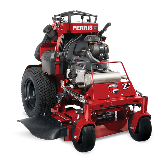
Page 3: Products Covered By This Manual
Thank you for purchasing this quality-built Ferris Zero- Turn Stand-On Mower. We’re pleased that you’ve placed your confidence in the Ferris brand. When operated and maintained according to the manuals, your Ferris product will provide many years of dependable service. - Page 4 Operating Safety Children Tragic accidents can occur with children. Do not allow them anywhere near the area of operation. Children are often Congratulations on purchasing a superior-quality piece of attracted to the unit and mowing activity. Never assume that lawn and garden equipment. Our products are designed and children will remain where you last saw them.
- Page 5 Thrown Objects Retaining Walls, Drop-Offs and Water This unit has spinning mower blades. These blades can pick up and throw debris that could seriously injure a bystander. Be sure to clean up the area to be mowed and remove objects that could be thrown by the blade BEFORE you start Retaining walls and drop-offs around steps and water are mowing. ...
-
Page 6: Slope Identification Guide
Only operate this unit outdoors and away from unventilated Note: A paper gauge slope identification guide is included areas such as inside garages or enclosed trailers. The in your product literature packet and is also available to engine emits poisonous carbon monoxide gas and prolonged download from the manufacturer's website. - Page 7 • Be sure all drives are in neutral and parking brake is engaged before starting engine. Only start engine from WARNING the operator’s position. Use seat belts if provided. It is a violation of California Public Resource Code, Section • Be sure of your footing while using pedestrian controlled 4442, to use or operate the engine on any forest-covered, equipment, especially when backing up.
- Page 8 operation. Children who have been given rides in the past may suddenly appear in the mowing area for another ride DANGER and be run over or backed over by the machine. Water, retaining walls and drop-off hazard • Never allow children to operate the unit. Wheels dropping over edges may result in serious injury, •...
-
Page 9: Safety Decals
• Always follow the engine manual instructions for proper procedures can result in hazardous operation, equipment start-up procedures when returning the unit to service. damage and voiding of manufacturer’s warranty. • Never store the machine or fuel container inside where there is an open flame, such as in a water heater. - Page 10 Part No.: 5105081 - Decal, Dash Panel, LH, Controls Part No.: 5105095 - Decal, Dash Panel, RH, Warning/Controls * Located near the transmission fans. Part No.: 7101665 - Decal, Danger Part No.: 5109418 - Decal, Warning, Fuel Overfill Part No.: 5104636 - Decal, Danger, Stand-On Part No.: 5061245 - Decal, Pinch Point Part No.: 5103184 - Decal, Warning, Hand in Pulley ferrismowers.com...
-
Page 11: Safety Icons
CAUTION indicates a hazard which, if not avoided, could result in minor or moderate injury. NOTICE indicates information considered important but not hazard-related. Safety Interlock System This unit is equipped with safety interlock switches. These safety systems are present for your safety, do not attempt to bypass safety switches, and never tamper with safety devices. - Page 12 specific sequences. To learn what combination and sequence of controls to use for various tasks see the Operation section. ) - Cutting Height Adjustment Pin ) - Storage Hole for Cutting Height Adjustment Pin Callout Description Deck Lift Lever, Cutting Height Adjustment Pin, and Deck Lift ) - Deck Lift Lock Lever Release Button Transmission Oil Fill (Transmission Oil Tanks)
- Page 13 The Maximum Forward Speed Bar can be adjusted in three • If the operator steps off the operator platform while the different positions to suit the desired maximum forward speed unit is running and the PTO switch is engaged, the PTO of the operator.
-
Page 14: Operation
Your machine is equipped with one of the different styles of choking. Pull the knob UP to close the choke. Push the knob hour meter listed below. DOWN to open the choke. Hour Meter (Displays Numbers Only): The hour meter Throttle Control: The throttle controls engine speed. -
Page 15: Checks Before Starting
1. While standing on the operator's platform, engage WARNING the parking brake, make sure that the PTO switch is • Never allow passengers to ride on the unit. disengaged, and that the ground speed control levers are • Before leaving the operator’s platform for any reason, in the NEUTRAL position. - Page 16 We suggest you begin with the Smooth Travel procedure, and then advance through the forward, reverse, and turning maneuvers. Prior to moving the ground speed control levers, the operator must be standing on the operator platform and the parking brake must be disengaged. Adjusting the Maximum Forward Speed Bar This zero-turn riding mower is equipped with an adjustable maximum forward speed bar (A, Figure 8), which is located...
- Page 17 Note: Straight forward travel takes practice. If the unit veers Practice Turning In Place to either direction while both ground speed controls levers are pressed against the maximum forward speed bar see Tracking Adjustment in the Maintenance Procedures section. Reverse Travel Practice To turn in place, “Zero-Turn,”...
-
Page 18: Operating On Slopes
This technique turns the rider LEFT and slightly overlaps Note: It is best practice to engage the PTO with the throttle the row just cut, eliminating the need to back up and re-cut set at the minimum throttle position necessary to engage the missed grass. - Page 19 The amount of grass you are able to cut in one pass is also If you hear the engine slowing down, you are mowing too effected by the type of mowing system you are using (for fast—using a slower ground speed will improve the cutting example, broadcasting with side discharge decks can process efficiency of the blades and prevents many common cutting a much larger volume of grass than mulching does).
-
Page 20: Pushing The Unit By Hand
manual gear models). If you hear the engine slowing down 2. Raise the operator support cushion to gain access to you are mowing too fast, use a slower ground speed. the transmission release levers (A, Figure 19) which are located on the back of the engine deck. There is How Much Grass to Cut Off When Broadcasting: one transmission release lever on each transmission. -
Page 21: Maintenance Schedule
manual to prevent the possibility of fire from the ignition of gasoline fumes. Remember, gasoline fumes can travel WARNING to distant sources of ignition and ignite, causing risk of Never store the unit, with gasoline in engine or fuel tank, explosion and fire. -
Page 22: Maintenance Procedures
UNIT MAINTENANCE Change hydraulic oil filter. ENGINE MAINTENANCE Before each use Check engine oil level. Clean visible debris from engine compartment and mower deck. Every 50 Hours Inspect / Clean spark arrester.** Every 100 Hours Check fuel filter. Refer to engine owner's manual Service air filter. -
Page 23: Check Engine Oil Level
6. Place an absorbent shop cloth under the engine oil filter Carbureated Models: The fuel filter is located in the fuel line (E). Remove the engine oil filter and replace with a new between fuel tank and carburetor, near the fuel pump. one. -
Page 24: Fuse Location And Identification
1. Locate the transmission oil tanks. The transmission oil tanks are located on the left side of the unit by the cut height pin box. 2. Check the oil level when the unit is cold. The oil should be up to the “FULL COLD” mark (B) on the transmission oil tanks. -
Page 25: Purging The Air From The Hydraulic System
• High operation temperature and excessive expansion of oil. Before starting, make sure the transaxles/transmissions are at the proper oil levels. If it is not, fill to the specifications outlined in the Check / Fill Transmission Oil Level procedure. Purging Air from the Hydraulic System: 1. - Page 26 Grease deck lift lever pivot block parking brake lever shaft lower parking brake shaft mower deck hanger linkages mower deck spindles Use grease fittings when present. Disassemble parts to apply grease to moving parts when grease fittings are not installed. Not all greases are compatible.
-
Page 27: Lubricate The Front Casters
Lubricate the Front Casters 2. Using a wrench, remove the bolt securing the blade to the spindle. Interval: Annually 1. Remove the 1/4-28 bolt (A, Figure 30) screwed into the Inspecting the Mower Blades caster and install a 1/4-28 grease fitting. DANGER Thrown objects hazard Avoid injury: a worn or damaged mower blade can break and a piece of the blade could be thrown into the operator's... -
Page 28: Cutting Height Adjustment
Sharpening the Mower Blades WARNING Thrown objects and fire hazard Grinding mower blades throws sparks and fine metal particles that are capable of igniting gasoline and gasoline vapors, and that can injure unprotected eyes. Be sure all flammable materials are cleared from the area where grinding will occur. -
Page 29: Neutral Adjustment
decal for the unit. This figure is intended to help you better 3. Pull the deck lift lever back towards the operator position understand the available cutting heights for this unit. and depress the deck lift release button (C, Figure 38) to release the transport position lock. ... - Page 30 brake, turn the ignition switch to OFF, and remove the 6. Tighten the jam nuts. ignition key. Left Hand Side Lockout Bolt Adjustment 2. Chock the front wheels of the unit to prevent movement and disengage the parking brake. 3.
-
Page 31: Deck Lift Rods
Ground Speed Control Lever Alignment Tracking Adjustment Adjustment 1. Park the machine on a flat, level surface such as a concrete floor. Disengage the PTO, engage the parking 1. Observe the alignment of the right side ground speed brake, turn the ignition switch to OFF, and remove the control lever (A, Figure 43) as compared to the left side key. ... -
Page 32: Deck Lift Assist Springs
3. Verify that the tires are inflated to the correct pressure. 4. Verify that the mower blades are flat, and not bent or broken. A bent or broken blade must be replaced. WARNING Avoid Injury! Mower blades are sharp. Always wear gloves when handling blades or working near blades. -
Page 33: Pto Drive Belt Replacement (36" Mower Decks)
Although it is fastened with a multi-position anchor, this is not an adjustment point. WARNING Do NOT attempt to adjust the spring length or lifting Use extreme caution when rotating the idler arm with the performance will be compromised. breaker bar, due to the increased tension in the spring as the idler arm is being rotated. -
Page 34: Mower Deck Drive Belt Replacement (36" Mower Decks)
3. Remove the PTO drive belt. See PTO Drive Belt Replacement (36" Mower Decks) for removal instructions. 3. Loosen the jam nut (C) on the eye bolt (D). 4. Turn the adjustment nut (E) until the measurement of 8-1/2" (21,6 cm) is achieved. WARNING Use extreme caution when rotating the idler arm with the 5. -
Page 35: Mower Deck Drive Belt Replacement (48" Mower Decks)
WARNING Use extreme caution when rotating the idler arm with the breaker bar, due to the increased tension in the spring as the idler arm is being rotated. Injury may result if the breaker bar is prematurely released while the spring is under tension. -
Page 36: Transaxle Drive Belt Replacement
Transaxle Drive Belt Replacement 7. Using a 1/2” breaker bar, place the square end in the Figure 54 depicts the transmission drive belt as seen from opening in the idler arm (G) and rotate the idler arm underneath the unit and looking up at it. The arrow (A, Figure clockwise, which will relieve the tension on the belt 54) indicates the front of the unit. -
Page 37: Parking Brake Adjustment
To Adjust the Lower Mounting Position: 3. Measure the distance (B) from the top of the threaded 1. Park the machine on a flat, level surface. Disengage the parking brake shaft (C) to the top of the adjustment nut PTO, engage the parking brake, turn the ignition switch to (D). -
Page 38: Battery Service
2. Add distilled water sufficient to cover the plate (fill to the proper level near the end of the charge). If the battery is extremely cold, allow it to warm before adding water because the water level will rise as it warms. Also, an extremely cold battery will not accept a normal charge until it becomes warm. -
Page 39: Troubleshooting
11. Remove the other cable by disconnecting at the discharged battery first and then disconnect the opposite end from the booster battery. 12. Discard the damp cloths that were placed over the battery vent caps. WARNING Any procedure other than the preceding could result in: (a) personal injury caused by electrolyte squirting out the battery vents, (b) personal injury or property damage due to battery... - Page 40 Problem: Engine will not turnover or start. Problem: Engine runs but mower will not drive. Engine flooded. Carbureted Models: Move choke Transmission drive belt is slipping. See problem and cause below. control to the closed position. Fuel Brake is not fully released. See authorized service dealer.
-
Page 41: Troubleshooting Common Cutting Problems
Problem: Mower deck drive belt slips or fails to drive. Problem: Stepped Cutting Cause Remedy Idler pulley spring broken or not Repair or replace as needed. properly attached. Mower deck drive belt is broken. Replace mower deck drive belt. Problem: Mower (blades) does not engage. Cause Remedy Electrical wiring damage. -
Page 42: Warranty
ENGINE Models with 36" Mower Decks For complete engine specifications see the engine Height 47" (119,4 cm) manufacturer's operator's manual included with your unit. Weight (approx.): 813 lbs (368,8 kg) Models with 48" Mower Decks Fits models: 5901546 & 5901678 Overall Length 65"... - Page 43 Briggs & Stratton products. ABOUT YOUR WARRANTY Warranty service is available only through Ferris Authorized Service Dealers. This warranty only covers defects in materials or workmanship. It does not cover damage caused by improper use or abuse, improper maintenance or repair, normal wear and tear, or stale or unapproved fuel. ...
Need help?
Do you have a question about the SRS Z1 Series and is the answer not in the manual?
Questions and answers