Sign In
Upload
Manuals
Brands
Sensia Manuals
Measuring Instruments
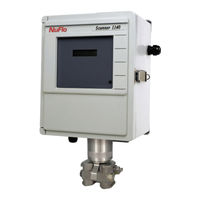
NUFLO Scanner 1140C
Sensia NUFLO Scanner 1140C Manuals
Manuals and User Guides for Sensia NUFLO Scanner 1140C. We have
1
Sensia NUFLO Scanner 1140C manual available for free PDF download: User Manual
Sensia NUFLO Scanner 1140C User Manual (132 pages)
RTU Hardware
Brand:
Sensia
| Category:
Measuring Instruments
| Size: 7 MB
Table of Contents
Table of Contents
5
Introduction
9
Overview of the Scanner 1140
9
Scanner Software
10
Scanners 1140T, 1140C, 1140L, and 1140G
10
Chapter 1: Installation
11
Quick Start
11
Operating/Storage Limitations
12
Unpacking
12
Mounting
12
Piping
12
Typical Installation of Scanner 1140T
13
Typical Installation - Scanner 1140C/L Integral Communications
14
Typical Installation (with Remote Communications)
15
Power Supply Connection
16
Power Supply
16
6-Volt Battery Power Supply, Division 1 Controller
16
Scanner 1140T (with Battery Cover Removed)
17
12-Volt Battery Power Supply, Division 2 Controller
18
Scanner 1140C (Front View with Door Open)
18
Scanner 1140L (Front View with Door Open)
19
Scanner 1140G
19
Solar Panel Installation and Connection
20
Flashing the Scanner
21
Getting Ready to Flash
21
Configuration Lock Switch
22
Start Flashing
22
Flashing with Scanflash
23
Flashing with Winsload (in Windows)
24
Installing Winsload
24
Using Winsload
24
Flashing with Scanload (DOS)
26
Installing Scanload Version 2.2
26
Using Scanload
27
Troubleshooting the Flashing Procedure
27
Startup Procedure
28
Superbooting the Scanner
28
Chapter 2: Main Board and Wiring
31
Main Circuit Board Diagram (Major Components)
31
Main Board Wiring Diagram
32
Field Termination
33
DIP Switch Summary
34
Memory Switches
35
Switch Control DIP Switch (SW4) Summary
35
Superboot Switch
37
Lithium Battery Switch
37
Analog Transmitter Inputs (Resources A09 - A10)
38
Analog 4-20 Ma Transmitter
38
Analog 1-5 VDC Transmitter (Txpwr)
38
Analog 4-20 Ma Output (Optional)
38
RTD Inputs (Resource A08)
39
Frequency Pulse Inputs (Resource A07)
40
Frequency Pulse Input DIP Switch (SW1) Summary
40
Three-Wire Preamplified Turbine (Barton 818) 0-5V Output
41
Two-Wire Preamplified Turbine (Barton 818) 0.5 - 5.5 Ma Output
42
Two-Wire Preamplified Turbine (Barton 818) 7-12 Ma Output
43
Open Collector Without "Bounce
44
Magnetic Pickup Coil
44
Dry Contact
45
Pepperl & Fuchs Inductive Proximity Sensor
45
Status Inputs and Outputs (Resources A03, A04, A05 and A06)
46
Console Serial Port (Resource A21)
46
Auxiliary Serial Port (Resource A02)
47
Rs-232C
47
Auxiliary Serial Port Optional DIP Switch (SW3)
48
MVX-II Wiring (RS-485 Communications)
49
Chapter 3: Optional Board and Wiring
51
MIO1 Expansion Board
51
Specification
51
General
51
Serial Port
51
Analog Output
52
Status In/Status Out/Pulse Outputs
52
Pulse Inputs
52
I/O Termination
53
Configuration Switches
55
Status Input/Output and Pulse Output Circuits
55
Serial Port Switches
55
Pulse Input Switches
55
Pulse Input Mode Select Switch Settings
56
Analog Output Switch
58
Circuit Board Wiring Diagrams
59
MIO1 Installation Procedure
62
Chapter 4: Troubleshooting
63
Tools Required
63
Problems and Solutions
63
Transmitter Voltage
67
Main Battery Voltage
68
NVRAM Lithium Battery Voltage
69
NVRAM Battery Change Procedure
69
Returning the Scanner
70
Chapter 5: Dpe+ Installation
71
DPE+ Installation
71
Replacing a DPE with a DPE+ Transducer
71
Gasket Options
72
Installing the Barrier Adapter (for Class I, DIV. 1 Installations Only)
74
Chapter 6: Principles of Operation
77
Application Software
77
Audit Trail
77
Central Processing Unit (CPU)
78
Memory
78
Fpga
78
Hardware Write Protection
79
Clocks
79
The Watchdog Timer
79
Power Management
79
Battery Power Options
79
Transmitter Supplies
80
Communications
80
Analog Inputs
80
RTD Inputs
81
Pulse Inputs
81
Front Panel
82
Standard Display
82
Autoscroll
83
Barton DPE+ Cell
83
Chapter 7: System Specifications
85
General Specifications
85
Environmental
85
Enclosure
85
Components
85
Computer
86
System Board I/O Summary
86
Expansion Board Interface
87
Display
87
Keypad (Optional)
87
Communications Port
87
Status In, Status Out, Pulse out
88
Rtd
88
Analog Inputs
88
Pulse Input Board (Optional)
89
Analog Output Board (Optional)
89
DPE+ Multi-Variable Transducer
90
Transmitter Power Supply
91
Power Supply Options
91
Volt Rechargeable Battery
92
Alkaline Battery
92
DC Input
92
12 Volt Rechargeable Battery
93
Software
93
Order Code
94
Outline Dimensions
97
Scanner 1140T (Front View)
97
Scanner 1140T (Side Views)
98
Scanner 1140C (Front View)
99
Scanner 1140C (Endcap Mount Side View)
100
Scanner 1140C (Universal Mount Side View)
101
Scanner 1140G (Top View)
102
Scanner 1140L (Front View)
103
Scanner 1140L (Side View of Enclosure)
103
Scanner 1140L (Side View of Enclosure)
104
Chapter 8: Parts List
105
Scanner 1140T
105
Scanner 1140C
109
Appendix A: Installation Drawings
115
Advertisement
Advertisement
Related Products
Sensia NUFLO Scanner 1140G
Sensia NUFLO Scanner 1140L
Sensia NUFLO Scanner 1140T
Sensia NuFlo Scanner 2000
Sensia 103381133
Sensia 9A-203B050G01
Sensia 9A-203B050G02
Sensia 9A-203B050G03
Sensia 9A-203B050G04
Sensia Barton 306
Sensia Categories
Measuring Instruments
Controller
Control Systems
Receiver
Gateway
More Sensia Manuals
Login
Sign In
OR
Sign in with Facebook
Sign in with Google
Upload manual
Upload from disk
Upload from URL