Advertisement
Quick Links
PROPER USE GUIDELINES
Cumulative Trauma Disorders can result from the prolonged use of manually powered hand tools. Hand tools are intended for occasional use and low volume
applications. A wide selection of powered application equipment for extended-use, production operations is available.
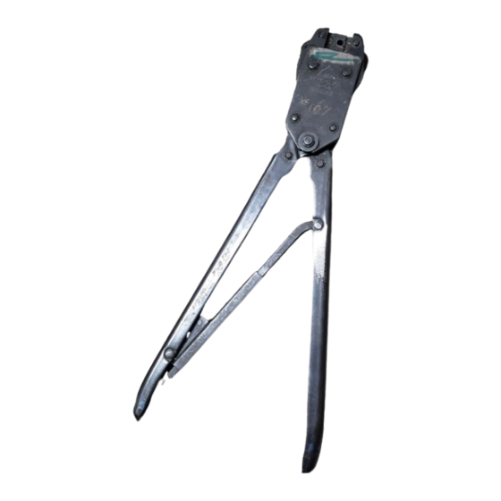
Anvils (Movable Die)
Locator
Handles
Figure 1
1. INTRODUCTION
Hand Tool Assembly 59282, shown in Figure 1, is
designed to crimp CERTI–SEAL* butt strap splice
assemblies listed in Figure 2 onto solid or stranded
wire sizes 16 through 14 AWG with an insulation
diameter range of 1.78 through 3.81 mm
[.070 through .150 in.].
Read these instructions carefully and completely
before using the tool.
Dimensions in this instruction sheet are in
NOTE
millimeters [with inches in brackets]. Figures and
illustrations are for reference only and are not
i
drawn to scale.
Reasons for reissue are provided in Section 6,
REVISION SUMMARY.
2. DESCRIPTION
The front of the tool, into which the wire is inserted, is
marked with the wire size range and tool part number.
E
2009 Tyco Electronics Corporation, Harrisburg, PA
All International Rights Reserved
TE logo and Tyco Electronics are trademarks.
*Trademark. Other products, logos, and company names used are the property of their respective owners.
Hand Tool Assembly 59282
The tool consists of a head and handle. The head
Crimpers (Fixed Die)
features two movable dies (wire anvil and insulation
anvil) and two fixed dies (wire crimper and insulation
Bottoming Surface
crimper). When closed, the dies form a crimping
of Dies
chamber. The locator is used to properly position the
splice in the crimping chamber.
Front of Tool
(Wire Side)
The CERTI–CRIMP hand tool ratchet control ensures
full crimping of the splice. Once engaged, the ratchet
will not release until the handles have been FULLY
closed.
3. CRIMPING PROCEDURE
CERTI-CRIMP*
Hand Tool
Ratchet Control
TOOLING ASSISTANCE CENTER 1-800-722-1111
PRODUCT INFORMATION 1-800-522-6752
The dies bottom before the ratchet releases. This
CAUTION
ensures maximum electrical and tensile
performance of the crimp. DO NOT re-adjust the
!
ratchet.
1. Refer to Figure 2, and choose the proper wire
size and insulation diameter for the splice. Strip the
wires to the dimension listed. DO NOT cut or nick
the wire conductor.
2. Close the tool handles until the ratchet releases.
CERTI-SEAL Butt Strap Splice Assembly
Window
Indent
Ring
Insulation Barrel
Wire Barrels
Note: Not to Scale
WIRE
INSULATION
SIZE RANGE
DIAMETER
(AWG)
RANGE
1.78-2.92
[.070-.115]
16 14
16-14
1.91-3.81
[.075-.150]
Figure 2
This controlled document is subject to change.
For latest revision and Regional Customer Service,
visit our website at www.tycoelectronics.com
Instruction Sheet
408-1537
13 MAR 09
Rev B
Wire Stop
Ring
Insulation Barrel
Wire Strip Length
(See Table)
Conductor
SPLICE
STRIP
LENGTH
7.87-8.38
324989
[.310-.330]
7.24-7.75
324549
[.285-.305]
1 of 4
LOC B
Advertisement

Related Manuals for Tyco Electronics 59282


Summary of Contents for Tyco Electronics 59282
- Page 1 Indent Ring 1. INTRODUCTION Ring Hand Tool Assembly 59282, shown in Figure 1, is designed to crimp CERTI–SEAL* butt strap splice assemblies listed in Figure 2 onto solid or stranded wire sizes 16 through 14 AWG with an insulation Insulation Barrel...
-
Page 2: Maintenance And Inspection
408-1537 Hand Tool Assembly 59282 3. Insert the splice into the crimping chamber until 3. Store tool in a clean, dry area with handles it butts against the locator with one end resting on closed. the anvils as shown in Figure 3. -
Page 3: Section 5, Replacement And Repair
Crimping Chamber Crimping Chamber parts is necessary. Parts other than those listed NO-GO NO-GO should be replaced by Tyco Electronics to ensure quality and reliability. Order replacement parts 4.064-4.072 4.265-4.267 3.353-3.360 3.503-3.505 through your Tyco Electronics Representative, or call [.1600-.1603]... - Page 4 408-1537 Hand Tool Assembly 59282 311.15 [12.25] 88.9 [3.5] Handles Closed REPLACEMENT PARTS ITEM PART NUMBER DESCRIPTION QTY PER TOOL 21045-3 Retaining Ring 300388-0 Retaining Pin 303863-0 Retaining Pin 303861-0 Retaining Pin 21045-6 Retaining Ring 306100-0 Key Insert Assembly 1-304197-4...
- Page 5 Mouser Electronics Authorized Distributor Click to View Pricing, Inventory, Delivery & Lifecycle Information: TE Connectivity 59282...
Need help?
Do you have a question about the 59282 and is the answer not in the manual?
Questions and answers