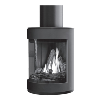
Table of Contents
Advertisement
Quick Links
PLEASE KEEP THESE INSTRUCTIONS FOR FUTURE REFERENCE
S50 Suspension Kit
INSTRUCTION MANUAL
Applicable for: 50-4074, 50-4298, 50-4299, 50-4300
This Suspension Kit has been tested for compliance to Standards:
ANSI Z21.88 and CSA 2.33.
This Suspension Kit has been approved for use on the ENVIRO S50 fireplaces only and must be installed at
the time of fireplace installation.
The following instructions must be followed in conjunction with the fireplace installation instructions to com-
ply with the standards and allow safe operation of the installed fireplace.
1
Advertisement
Table of Contents

Subscribe to Our Youtube Channel
Summary of Contents for Enviro S50
- Page 1 This Suspension Kit has been tested for compliance to Standards: ANSI Z21.88 and CSA 2.33. This Suspension Kit has been approved for use on the ENVIRO S50 fireplaces only and must be installed at the time of fireplace installation. The following instructions must be followed in conjunction with the fireplace installation instructions to com-...
-
Page 2: Safety Precautions
NEVER ALLOW CHILDREN shut. TO TOUCH GLASS. • If the S50 is pulled out of its installation, and the vent-air A barrier designed to reduce the risk of burns from the intake system is disconnected for any reason, ensure that... -
Page 3: Table Of Contents
Gas Flex Line Installation .........................13 Incoming Power Installation......................14 IMPORTANT Suspension kit is ONLY compatible with S50 models that have a ‘‘twist lock’’ top plate. NOT compatible with models that have the original top plate hinge system. (see pictures down below) -
Page 4: General Information
General Information This kit is the required starting point to suspend the S50 from a ceiling. This kit is to be combined with addi- tional 1ft and 2ft segments (50-4299 and 50-4300 respectively) to create the desired structure height to sus- pend your S50. -
Page 5: Kit Contents - 1Ft & 2Ft Sections
General Information - 1Ft & 2Ft s ontents eCtions Figure 2: 1ft Section Kit Contents (50-4299) Figure 3: 2ft Section Kit Contents (50-4300) Table 2: 1FT & 2FT Section Kit Content Descriptions Item Description Section Joint Plate (x4) 1ft Section Assembly Duravent DuraBlack 10”... -
Page 6: Framing And Clearances
[50-4299] 1ft Section Refer to section “Clearance to Combustibles” in the Owner’s Manual Min. Height - 18 ½” Figure 4: S50-S Installation Diagram Note: S50 Suspension Kits only work for flat ceilings. Not compatible with vaulted, cathedral or arched ceilings. -
Page 7: Installation
(457mm) (457mm) To better line up the ceiling mount with the final location of the S50, a string with a small weight at- tached can be slowly dropped through the center of the Ceiling Mount Assembly. 2. Secure the Ceiling Mount Assembly to the joists once the final location has been determined. -
Page 8: Unit Preparation
Figure 7: Wire Cover Removal structure with the top of the S50 as shown in Figure 9. The Air Box Joints will line up with three (3) holes on each side of the airbox. Secure in place using six (6) 1/4-20 Hex head bolts. - Page 9 7. Slide a vent piece through the center of the suspen- sion structure and attach to the exhaust adapter on the S50. 8. Retrieve the replacement S50 top cover and attach it to the unit following the same steps used to remove the stock top cover.
-
Page 10: Wiring & Gas
- Type of CSST used has a rated operating temperature limit of 180˚F (82˚C) or better - CSST must stop a minimum height of 6 ft (1.83m) above the top of the S50 and transition to copper tube or black iron pipe as shown in figure 10. Using CSST within the susspension structure closer than 6ft (1.83m) will expose it to temperatures above the maximum rating. - Page 11 Installation Power In Gas In 180˚F (82˚C) Rated CSST (if desired) Transition to 1/2” I.D. Copper or Black Iron 221˚F (105˚C) Rated Wire Gas Line Electrical Line Min. 6ft (1.83m) Connection point to suppplied high temperature mica wire 1-2ft (0.3-0.6m) Figure 10: Gas/Electrical Line Through Structure...
-
Page 12: Unit Installation
Dura Black 10” section. Gather these parts and slide them one-by-one over the suspension structure as shown in Figure 12. 5. Carefully lift the S50 and position it below the suspension structure. Thread the high-temp wires through the remaining suspension structure in the same way as the previous sections. -
Page 13: Gas Flex Line Installation
2. Route the supplied flex line down the left side of the S50 cabinet back as shown in the pictures below. Re- moval of the cabinet back will improve the ease of installation but is not required: 3/8 NPT fitting. -
Page 14: Incoming Power Installation
4. The new incoming power wires will need to be joined to the electrical circuit of the unit. This will vary based on the version of S50 being used. Refer to the electrical diagram in the Owner’s Manual for your unit and join the wires where the power cord is shown within the circuit. - Page 15 MANUFACTURED BY: SHERWOOD INDUSTRIES LTD. 6782 OLDFIELD RD. SAANICHTON, BC, CANADA V8M 2A3 www.enviro.com October 2023 C-16735...


Need help?
Do you have a question about the S50 and is the answer not in the manual?
Questions and answers