Table of Contents
Advertisement
Quick Links
Advertisement
Table of Contents

Related Manuals for Rice Lake Uni-9 Series


Summary of Contents for Rice Lake Uni-9 Series
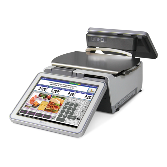
- Page 1 Uni-9 Series Scale and Printer Installation Manual PN 162299...
-
Page 3: Table Of Contents
Course descriptions and dates can be viewed at www.ricelake.com/training or obtained by calling 715-234-9171 and asking for the training department. © Rice Lake Weighing Systems. All rights reserved. Printed in the United States of America. Specifications subject to change without notice. - Page 4 5.2 DNS Servers..............45 Rice Lake continually offers web-based video training on a growing selection of product-related topics at no cost.
-
Page 5: Introduction
Failure to follow the instructions or heed the warnings could result in injury or death. Rice Lake Weighing Systems is not liable for any damage, loss or injury that results from incorrect operation, insufficient caution, unauthorized modifications to the scale, or failure to follow the instructions contained in this manual. -
Page 6: Menu Navigation
Menu Navigation 1. Select the desired menu on the left side of the screen – PROGRAM SETUP , or ADJUST The color of the icons indicates the selected menu. Figure 1-1. Uni-9 Program Menu and Navigation Tabs 2. Use and buttons to scroll through the menu pages. 3. -
Page 7: Menu Structure
Menu Structure Operation Total Program Setup Adjust Sales Daily Total Machine No. Time/Date ACC1 Weekly Total Campaign Sales Mode Touch Screen ACC2 Cummulative Total Operators Password Display Check ACC3 Traceability Total Preset Key Key Lock Sound Total Adjust Preset Report Ad Message Data Storage Firmware Detail... - Page 8 Feature Menu Step Comments Date & Time Adjust Date Time DHCP Setup Machine No. IP Addr. Display Capture Adjust Display Capture Press TARE, save to USB folder: "CAPTURE" Dual-Range Adjust Calibration Encryption Setup Machine No. WiFi Error Log Setup Error Log Forced Tare Setting Setup Error Process...
-
Page 9: Passwords And Menu Navigation
Passwords and Menu Navigation The availability of the menus is based on the password entered. The service password, 495344, PLU provides access to all menus. Refer to Section 1.3 for a list of all menu steps. 1.4.1 Service Access Password 1. -
Page 10: Installation And Setup
Installation and Setup Checking the Scale Firmware Before configuring a new scale, it is important to check the firmware version. The scale firmware is loaded from a USB memory stick. All service technicians working with the Uni-9 scale should have access to at least one USB memory stick. -
Page 11: Updating The Scale Firmware
9. Press 10. Press the Sales key to return to normal operation mode. Updating the Scale Firmware Firmware files are downloaded to the Uni-9 directly from a USB memory stick. Updating the firmware is a multi-step process. Before installing new firmware, the current database must be saved and the scale’s data files initialized. -
Page 12: Saving All Data
2.2.2 Saving All Data Backup the scale database to the USB memory stick. Output Select Scale>USB Figure 2-4. File Output to USB Memory Stick 1. Press to enter the Main menu. 2. Press 3. Enter the password 495344 and press to access hidden menu steps. - Page 13 ALL SEL. EXEC Message Figure 2-6. Select All Files and Output to USB Memory Stick 12. Press the ALL SEL. to select all files for output. See Figure 2-6. 13. Press EXEC, at the next screen, press EXEC again to send the files to the USB Memory Stick. The screen displays the progress of files being copied.
-
Page 14: Initializing Data
2.2.3 Initializing Data After backing up the database continue on to initialize (delete) the data files. ALL SEL. EXEC SCALE INT. Figure 2-7. Select all Files and Initialize 1. Press SCALE INIT 2. Press the . button to select all files to be initialized. ALL SEL 3. -
Page 15: Downloading Main Firmware
2.2.4 Downloading Main Firmware Load the firmware previously copied to the USB memory stick. 1. Confirm the USB memory stick is still in the USB port. Important Do not remove the USB memory stick during the firmware update procedure. 2. Turn on the scale. 3. -
Page 16: Clearing Memory
Message EXEC Figure 2-10. Begin Firmware Download 12. Press again to begin the firmware download. See Figure 2-10. EXEC 13. The screen will show the firmware download progress. The download will take several minutes to complete. 14. When Re-Boot Check message 15029-0002 is displayed, the firmware download is complete. -
Page 17: Downloading Sub-Application Firmware
7. Press to confirm the memory clear. EXEC 8. After the result is displayed, press Downloading Sub-Application Firmware After clearing the memory, download any sub-application firmware programs, as needed, based on the initial check of firmware versions (See Section 2.1 on page 6). 1. - Page 18 5. Select File Save/Load. INPUT SELECT USB > SCALE Figure 2-13. File Input from USB Memory Stick 6. Press the tab. USB>Scale 7. Press the Input Select key. Depending on the size of the data files, it may take up to 15 seconds to display a list.
-
Page 19: Installing A Plug-In
ALL SEL. EXEC Message Figure 2-14. Select All Files for Input 11. The screen displays the progress of files being copied. 12. Press , when restore is complete (message 14013-0000). 13. Press to exit. 14. Press the SALES key to return to normal operation mode. 2.5.1 Installing A Plug-In Use this procedure for installing a plug-in on the scale to add additional features. -
Page 20: Memory Clear
3. Enter 495344 and press to access hidden menu steps. 4. Press 5. Select DOWNLOAD Plug-in EXEC Figure 2-15. Plug-In Download 6. Press the plug-in to be loaded. It will highlight in yellow. 7. Press to confirm the selection. EXEC 8. -
Page 21: Basic Configuration
6. Perform both standard clears: Master Data and Test Data following the steps below. • Press , then press is displayed. CLEAR EXEC Master Data deletes all data in the Program menu and custom Label Formats. • Press , then press is displayed. -
Page 22: Calibration
11. Press Figure 2-18. Date and Time 12. Select DATE TIME 13. Press the DATE field to enter the current date. Enter the date in the format noted on the display. 14. Press to save the value. 15. Press the and choose the correct time zone from the list. - Page 23 11. Remove the weight and confirm the A/D counts return to 20000. If not, repeat Step 8 to Step 10. 12. Remove the weigh platter. Figure 2-20. Calibration Save Button Access with Plate Removed 13. Remove the small counter sink screw and seal bolt to remove the metal access plate covering the calibration access hole.
-
Page 24: Ethernet Configuration
Ethernet Configuration This section covers setting the Uni-9 IP Address, Subnet Mask, etc. After completing this section, refer to Section 3.1 to complete communications setup of wireless scales. If the wireless option is installed but the scale will be hardwired to the network, disconnect the patch cable from the internal bridge connected to the scale's LAN port. -
Page 25: Wireless Configuration
11. Select the tab. PC COM . Refer to Section 3.2 on page 24 for 12. If using , press and cycle the power of the DHCP Uni-9 configuration. DHCP 13. Press the field to enter a computer IP Address to be used for comms testing from the scale PC IP ADDRESS (ping). - Page 26 4. Press 5. Select MACHINE No. Figure 3-4. Initial WiFi (Wireless) Configuration Screen 6. Select the WiFi tab. 7. Press the SSID (Wireless Network Name) field. 8. Enter the Network Name assigned to the Access Point(s) or Wireless Router(s). The Network Name is always case sensitive. Example: Scales. 9.
- Page 27 11. The new SSID Network Name is displayed Encryption Key Field Figure 3-6. Select Encryption Settings 12. Select the appropriate type. SECURITY / AUTHENTICATION / ENCRYPTION Example: WPA2 PSK TKIP. NONE If no encryption will be used press and proceed to step 19. An Encryption setting of NONE does not disable wireless communication.
-
Page 28: Dhcp Configuration
19. Press to save and change the WiFi settings (message 14059-0009). EXEC Message Figure 3-7. Press OK then Wait at Least 30 Seconds PLEASE WAIT 30 SEC TO ENABLE WiFi SETTINGS (message 14059-0010) will display, press Wait at least 30 seconds after pressing the OK button. The new wireless settings will not be stored if Important sufficient time is not provided. -
Page 29: Browser Configuration
6. Select tab. IP ADDR 7. Select under DHCP MODE 8. Cycle power to the scale. When scale reboots, all Ethernet settings will be populated. Browser Configuration With the browser function, the operator can browse a website either by entering the URL at the operation Uni-9 mode or just press the preset key with the URL assigned. -
Page 30: Programming Browser Preset Key
3.3.3 Programming Browser Preset Key 1. Press to enter the main menu. 2. Press 3. Select the key. PRESET Figure 3-10. Preset Key Menu 4. Select to highlight the row. MAIN 5. Press the DETAIL 6. Press then press There must be space available on the screen for the key to work. - Page 31 Figure 3-12. Linux System Menu 5. Type in lowercase into the command prompt, then press sudo pcmanfm ENTER 6. Select SYSTEM from the left list. 7. Select the folder and press ENTER 8. Select the environment file from the list and press ENTER 9.
-
Page 32: Scale Configuration
Scale Configuration Backup and Restore by USB Memory Stick Configuration and data files may be saved to a USB Memory Stick. The files can then be loaded into another Uni-9 scale or retained as a backup. Up to ten backup files may be stored on a USB Memory Stick. 4.1.1 Backup Data Files from Scale 1. -
Page 33: Restore Data Files To Scale
Figure 4-2. Select All Files for Output 14. Press the key to select all files for output. Selected files are highlighted. Individual files may be ALL SEL. selected, but backing up all files is recommended. 15. Press EXEC twice to send the files to the USB Memory Stick. The screen displays the progress of files being copied. -
Page 34: Label Setup
Figure 4-3. USB Memory Stick Input to Scale Memory 9. Press . Depending on the size of the files it may take up to 15 seconds to display a list. INPUT SELECT 10. Press the desired file number. The line will highlight. - Page 35 5. Select . The current label cassette is highlighted in yellow. CASSETTE Figure 4-5. Label Cassette Setup 6. Select the white field (lower right), enter the label format number, press Numeric Entry SET. 7. Select the highlighted LABEL FORMAT NUMBER field.
- Page 36 17. Set the to one of the selections below: OVERFLOW FLAG • – if the PLU name is too large to fit completely in the available area, an error will ERROR + BLANK display and the PLU name will be blank (default). •...
-
Page 37: Label Specification
Figure 4-6. Label Specifications (default settings) 8. Press to return to Normal Operation mode. SALES Under normal circumstances, there is no need to alter the Label Specifications. If changes are required please consult Rice Lake Retail Solutions technical support. Scale Configuration... -
Page 38: Advertising Messages
Advertising Messages This section covers programming Advertising Messages which are shown on the scale’s customer side display. Text, images, and video may be included in the messages. The images and video linked to the Advertising Messages are downloaded to the scale using SLP-5. 4.3.1 Basic Configuration of Ad Messages 1. - Page 39 12. Enter the . Based on the display speed setting, this is either the number DISPLAY COUNT / DISPLAY TIME of consecutive times or the length of time the message is displayed. If the Screen Saver is set as Yes, set the value equal to the number of images or videos assigned to the Ad Message.
-
Page 40: Video Ad Messages
4.3.2 Video AD Messages 1. Find or select a video to use for an advertisement message. Figure 4-10. KeepVid Website 2. If the video is on the Internet, copy the URL link or the file path of the video and navigate a web browser to www.keepvid.com. - Page 41 10. Create a new AD Message or select an existing message to edit: • Press the button and if there are no messages. EXEC • Press the white numeric entry field (lower right), enter an unused number and press EXEC •...
-
Page 42: Departments
Departments With the department function, operators can call up specific PLUs for a specific department on a scale. The PLU list will only show the PLUs associated with the assigned department. 4.4.1 Using Designated Leading Digits of PLU No. As Department No. 1. -
Page 43: Utilizing A Cassette Function
4.4.2 Utilizing A Cassette Function 1. Press to enter the Main menu. 2. Press 3. Enter and press to access hidden menu steps. 495344 4. Press 5. Select Cassette. 6. Press the Right Arrow key until the last page that shows NETWORK No. -
Page 44: Top Sellers
8. Select 9. Select PRESET KEY 10. Touch to highlight it, then press the key. MAIN DETAIL 11. Press and then . Space must be available for a new key to be created. 12. Select No. 435 from the list. CAST. -
Page 45: Programming The Scheduler For Top Sellers
Figure 4-19. Key Edit 8. Press the key and assign a ranking to . A specific item can be designated as a top seller all EDIT SUBDATA the time regardless of actual production. To do this, assign the PLU No. to DATA. 9. -
Page 46: Vnc Viewer
Figure 4-22. Scheduler and Detail Tabs 11. Set the date and time for the scheduler to update. Start and end time must be the same. 12. Select the days of the week the scheduler is to start. 13. Select the DATA 14. -
Page 47: Team Viewer
Team Viewer This section covers how to setup the scale for remote access through Team Viewer. 1. Install Team Viewer onto the PC that will be remotely accessing the scale. 2. Download the team viewer plug-in (J0845B) to the scale. See Section 2.5.1 on page 15. Once the team viewer plug-in is installed, the scale will reboot. - Page 48 Figure 4-25. Team Viewer 19. Once connected, the ID and Password for the partner to log in is displayed. 20. Press CTRL+F12 to enable the Uni-9 cursor on the PC side. Uni-9 Installation Manual...
-
Page 49: Appendix
Appendix Proxy Servers Proxy servers are computers that act as a gateway between a local network and larger networks, like the Internet. A proxy server connects to, responds to and receives traffic from the Internet. They funnel Internet connections through their own connection, which gives network administrators a way to track and control Web access. To find out if the network is using a proxy server follow the steps below. - Page 51 230 W. Coleman St. • Rice Lake, WI 54868 • USA U.S. 800-472-6703 • Canada/Mexico 800-321-6703 • International 715-234-9171 • Europe +31 (0)26 472 1319 www.ricelake.com www.ricelake.mx www.ricelake.eu www.ricelake.co.in m.ricelake.com © Rice Lake Weighing Systems 03/02/2015 PN 162299...
Need help?
Do you have a question about the Uni-9 Series and is the answer not in the manual?
Questions and answers