
Related Manuals for GABOR Levitouch DM-550


Summary of Contents for GABOR Levitouch DM-550
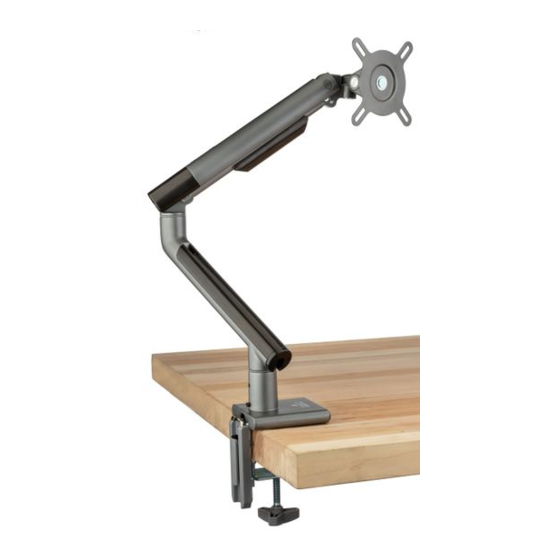
- Page 1 DM-550 / LEVITOUCH SINGLE ARM MONITOR MOUNT for 17 to 32 in. Desktop Computer Monitors User Manual...
- Page 2 Thank you for choosing Gabor. The Gabor Single-Arm Desktop Mount can securely support a monitor from 17 to 32 inches. The stylish yet rugged aluminum build will hold a monitor weighing up to 19.8 pounds, and the adjustable spring tension mechanism makes it easy to move your monitor to the perfect viewing height.
-
Page 3: Safety Warnings
Safety Warnings • Please read and follow the instructions, and keep this manual in a • Do not exceed the maximum load capacity. safe place. • Do not install this product on an unsteady structure or one that is • To avoid damage to this product, be careful not to overtighten or prone to vibration, has a chance of being impacted, or is susceptible improperly thread any of the threaded fittings. -
Page 4: Product Specifications
Product Specifications Monitor display size Monitor arm swivel 187mm 253-292mm 70mm 17 to 32 in. (43.2 to 81.3 cm) ±180° Maximum weight per monitor Base arm pivot 19.8 lb. (9 kg) ±90°/±180° Maximum desktop thickness Arm height adjustment 3.1 in. (8 cm) 6.9 to 17.1 in. - Page 5 Overview VESA lock VESA receiver Monitor arm VESA plate Tension indicator Rotation tension screws End cap Tilt tension screw Arm tension Top cable guide screw Monitor arm setscrew Bottom cable guide Grommet hole Base arm Swivel setscrew Base socket Base arm setscrew Base Clamping flange Flange...
-
Page 6: Parts Included
Parts Included Required tool Optional tool (grommet installation) Phillips screwdriver Drill with 3/8 in. bit M4 × 12 mm screws M5 × 12 mm screws D5 washers Monitor arm Base arm VESA plate Clamp Flange Base Notch cover Clamping flange Carriage bolt Flat hex screws Washer... -
Page 7: Clamp Installation
Clamp Installation Attach the flange (E) to the base (F) with the three hex screws (J). Tighten them with hex key (N) until secure. Before you attach the clamp to the flange, Important! The clamp should rest on the flange measure the thickness of the table or bolts. - Page 8 Grommet (Non-edge) Installation Important! Predrilled holes in the desktop should be between of 0.4 to 2.4 inches (10 to 60 mm) in diameter. If you need to drill a hole in Cover the hex the desktop, use a 3/8-inch screws with the plastic caps (M).
- Page 9 Attaching the Arm Note: The base arm should easily slide completely into its socket. If it doesn’t, loosen the base arm setscrew before reinserting the arm into its socket. Fit the base arm (B) into the base socket. Insert the monitor arm (A) into the base arm socket. Use the screwdriver end of hex key (N) to tighten the base Use the screwdriver end of hex key (N) to tighten the monitor arm setscrew until secure.
- Page 10 Attaching the VESA Plate to the Monitor Important! Before you attach the VESA plate, hand thread one of the M-A or M-B screws to determine which one fits your monitor. Make sure the screw is also not too long or too short.
-
Page 11: Attaching The Monitor
Attaching the Monitor Once the VESA plate is securely attached to the monitor, slide it into the VESA receiver. Turn the VESA lock to the locked position. UNLOCKED Important! The VESA lock secures the VESA plate inside the VESA mount and ensures the monitor won’t lift out of the mount when you adjust the monitor height. -
Page 12: Balancing The Arm
Balancing the Arm You can adjust the arm tension to balance the arm according to the weight of your monitor. Remove the end cap from the arm to expose • If the arm drops, tighten the arm tension screw by the arm tension screw. - Page 13 Adjusting Tilt and Rotation Tilt and rotation adjustments determine how easily and smoothly you can adjust the screen’s position. Rotation Tilt The monitor should rotate easily, but once it’s set at If the monitor doesn’t stay at the desired tilt angle, the proper orientation it should stay there.
- Page 14 Adjusting Arm Swivel The arm can swivel +/-180°. However, if the stand is in front of a wall or cubical that can be damaged from contact with the arm or monitor, the arm rotation can be limited to +/-90°. To limit arm swivel to +/-90°, tighten the swivel setscrew on the back of the base arm socket with the screwdriver end of hex key (N).
-
Page 15: Organizing Cables
Store the Hex Keys Organizing Cables Power and monitor cables can be neatly Store the hex keys and keep them run through the top and bottom cable handy for future adjustments by guides on the arms. sliding them into the holes on the back of the flange. - Page 16 To obtain warranty coverage, contact the Gabor Customer Service Department to obtain a return merchandise authorization (“RMA”) number, and return the defective product to Gabor along with the RMA number and proof of purchase. Shipment of the defective product is at the purchaser’s own risk and expense.
Need help?
Do you have a question about the Levitouch DM-550 and is the answer not in the manual?
Questions and answers