Table of Contents
Advertisement
Quick Links
Advertisement
Table of Contents

Related Manuals for GABOR FSM-M


Summary of Contents for GABOR FSM-M
- Page 1 FSM-M / FULL SWING MOUNT for Medium Flat-Panel Displays User Manual...
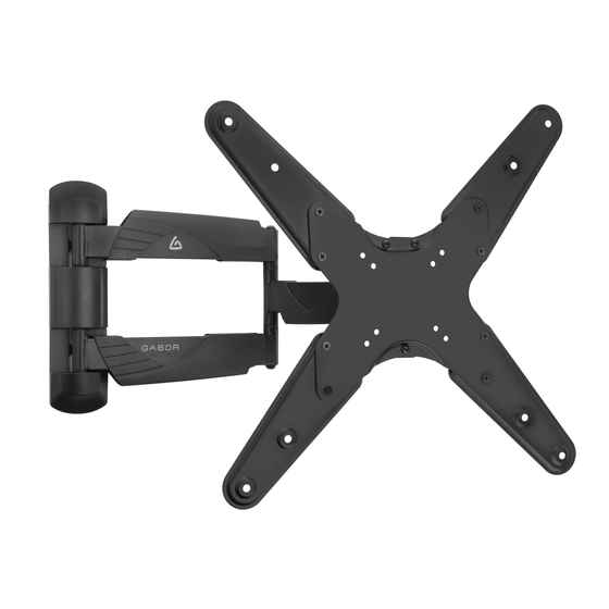
- Page 2 Thank you for choosing Gabor. This Gabor Full-Swing Wall Mount offers flexible mounting and customizable viewing angles for wall-mounted TVs and monitors. It accommodates flat-panel displays with screen sizes measuring 25 to 55 inches. The sturdy steel construction supports a maximum weight of 77 pounds. The mount offers post-installation adjustments for tilt, swivel, pan, screen depth, and horizontal level—...
-
Page 3: Safety Warnings
• This product may contain small parts which can possibly pose a professional or installation contractor; Gabor takes no responsibility choking hazard; keep out of reach of children and pets. for any product damage or personal injury resulting from mishandling, incorrect mounting, faulty assembly, or improper use of this product. -
Page 4: Product Specifications
Product Specifications Depth from Mounting Source Max Weight Capacity 1.8 to 20 in. (4.6 to 50.8 cm) 77 lb. (34.9 kg) Recommended Screen Sizes Material 25 to 55 in. (63.5 to 139.7 cm) Steel Weight VESA Mounting Patterns 8.6 lb. (3.9 kg) 75×75 mm 100×100 mm 200×100 mm... -
Page 5: Required Tools
Overview Required Tools Wall M5 × 14 mm screws M6 × 14 mm screws M6 × 30 mm screws M8 × 30 mm screws bracket Drill Phillips screwdriver M8 × 50 mm screws D5 washers D8 washers Small spacers Hammer Stud finder Display Large spacers... - Page 6 Display/TV Placement Before installing the Gabor Full Swing Mount, you will need to determine the placement of your display and identify surrounding support structures for attachment. The best height for a display is at the viewer’s eye level. You can find this height in one of two ways.
- Page 7 Preparing the Wall Bracket Preparing the Wall Bracket Remove the Display Mounting Plate Remove the Center Cover Loosen the top nuts slightly, then remove the bottom nut as shown. Slide the plate out from the wall bracket.
- Page 8 VESA mounting patterns 75 × 75 100 × 100 200 × 100 200 × 200 VESA patterns with mounting plate arms attached 300 × 300 400 × 200 400 × 400...
- Page 9 Attaching the Mounting Plate Arms...
- Page 10 Attaching the Display Mounting Plate Selecting the Right VESA Mounting Hardware for Your Display A variey of screws are included to fit VESA standards on the backs of most displays. Select the screws that best fit your display. If Your Display Has Recessed Hand-thread the screws to determine the Mounting or a Curved Back: If the screw is...
- Page 11 Attaching the Wall Bracket to Wooden Studs Wooden studs run vertically inside the wall, 16 inches apart, behind the drywall or plaster. The wall bracket must be mounted to a wooden stud, or the bracket could fall out and damage your display or cause personal harm. 3/16 in.
- Page 12 Attaching the Wall Bracket to Wooden Studs (cont.) Attach the bracket to the wall by inserting Attach the center cover and two end covers. Wall bracket mounted to wooden stud, with correct screw placement. the three anchor screws through the washers and the wall bracket’s mounting holes, and screw them into the predrilled support holes until secure.
- Page 13 Attaching the Wall Bracket to Concrete Warning! Make sure the concrete wall is solid and at least 8 inches (20 cm) thick. If the concrete exhibits cracks or other defects, this may result in failure of the concrete anchors and cause serious personal injury or damage to your display. 3/8 in.
- Page 14 Attaching the Wall Bracket to Concrete (cont.) Attach the bracket to the wall by inserting Attach the center cover and two end covers. Wall bracket mounted to concrete, with correct screw placement. the anchor screws through the washers and the wall bracket’s mounting holes, and screw them into the anchors until secure.
- Page 15 Mounting the Display on the Wall Bracket Important! We recommend that two people perform this step. Make sure the two top nuts are attached and slightly loose. Lift your Replace the bottom hex nut and then tighten all three hex nuts using display up to the wall bracket, and seat the display into the mounting the box end wrench.
- Page 16 Post-Installation Adjustment Once your display is mounted on the wall bracket, you can fine-tune adjustments to the horizontal level +3° to -3°, depth from the wall 1.8 to 20 inches, tilt +10° to -15°, and pivot 180°. +3° -3° +10° -15°...
- Page 17 Post-Installation Adjustment (cont.) 180° 180° 180° 1.8-20 in. Display Pivot Display Depth Pivot your display up to 180° for flexible mounting in the corner of a You can collapse or extend the mount so your display is 1.8 to 20 inches room or around an object.
-
Page 18: Cable Management
Cable Management Run the power and A/V cables through cable covers on the top or bottom of the wall bracket extension arms. Widen the cover openings to remove and slide the covers over the arms as shown. -
Page 19: Five-Year Limited Warranty
To obtain warranty coverage, contact the Gabor Customer Service Department to obtain a return merchandise authorization (“RMA”) number, and return the defective product to Gabor along with the RMA number and proof of purchase. Shipment of the defective product is at the purchaser’s own risk and expense. - Page 20 MADEBYGABOR WWW. .COM...
Need help?
Do you have a question about the FSM-M and is the answer not in the manual?
Questions and answers