
Related Manuals for SIGMATEK CP 111-1


Summary of Contents for SIGMATEK CP 111-1
- Page 1 CP 111-1 S-DIAS CPU Module Operating Manual Date of creation: 10.02.2022 Version date: 03.02.2022 Article number: 20-004-111-1-E...
- Page 2 (print, photocopy, microfilm or in any other process) without express permission. We reserve the right to make changes in the content without notice. SIGMATEK GmbH & Co KG is not responsible for technical or printing errors in this handbook and assumes no responsibility for damages that occur through its...
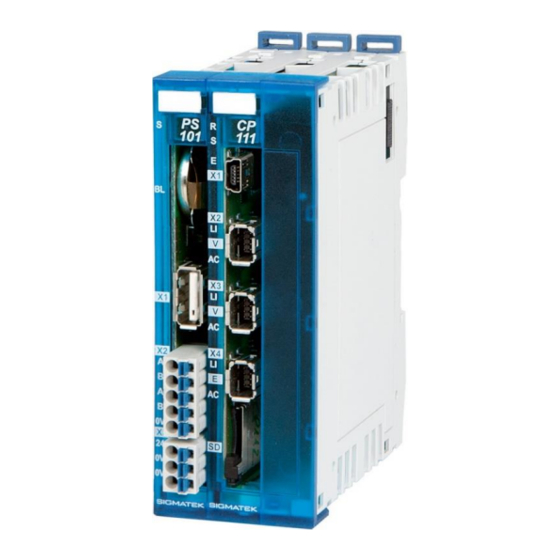
- Page 3 1 microSD 1 USB-Host 1 CAN The S-DIAS CP 111-1 CPU module is a high-performance processor unit for the S-DIAS I/O modules. Through the various interfaces, such as Ethernet, 2x VARAN, CAN bus, USB and an exchangeable microSD card, this module can be used for a variety of applications.
-
Page 4: Table Of Contents
CP 111-1 S-DIAS CPU MODULE Contents Introduction ................5 Target Group/Purpose of this Operating Manual ...... 5 Important Reference Documentation ......... 5 Contents of Delivery ..............5 Basic Safety Guidelines ............6 Symbols Used ................6 Disclaimer ..................8 General Safety Guidelines ............9 Software/Training ............... - Page 5 S-DIAS CPU-MODULE CP 111-1 Connector Layout ..............19 Status LEDs Interface Part ............20 Status LEDs Supply Part ............21 PS 101 Connector ............... 22 CP 111 Connector ............... 23 Applicable Connector Cables ............ 25 Applicable Connectors ............... 26 Label Field ................... 27 Mounting ................
- Page 6 21.3 Shielding for Wiring Within the Control Cabinet ..... 53 21.4 Connecting Noise Generating Components ......54 21.5 Shielding Between Two Control Cabinets ....... 55 22 Working with and on the CP 111-1 ........56 23 Disposal ..................57 Page 4 10.02.2022...
-
Page 7: Introduction
Our support team is happily available to answer your questions. Please see our website for our hotline number and business hours. Important Reference Documentation This and additional documents can be downloaded from our website or obtained through SIGMATEK Support. Contents of Delivery 1x CP 111-1 10.02.2022 Page 5... -
Page 8: Basic Safety Guidelines
CP 111-1 S-DIAS CPU MODULE Basic Safety Guidelines Symbols Used The following symbols are used in the operator documentation for warning and danger messages, as well as informational notes: DANGER Danger indicates that death or serious injury will occur, if the specified measures are not taken. - Page 9 S-DIAS CPU-MODULE CP 111-1 Danger for ESD-sensitive components. Les signes de danger pour les composants sensibles aux décharges électrostatiques. 10.02.2022 Page 7...
-
Page 10: Disclaimer
Please thoroughly read the corresponding documentation and this operating manual before handling a product. SIGMATEK GmbH & Co KG is not liable for damages caused through non-compliance with these instructions or applicable regulations. Page 8... -
Page 11: General Safety Guidelines
2006/42/EG guidelines is correct. As long as the machine with which the product should be used does not comply with the guideline, operating this product is prohibited. Operate the unit with devices and accessories approved by SIGMATEK only. 10.02.2022 Page 9... - Page 12 CP 111-1 S-DIAS CPU MODULE CAUTION Handle the device with care and do not drop or let fall. Prevent foreign bodies and fluids from entering the device. The device must not be opened, otherwise it could be damaged! Manipulez l’appareil avec précaution et ne le laissez pas tomber.
-
Page 13: Software/Training
S-DIAS CPU-MODULE CP 111-1 Software/Training The application is created with the software LASAL CLASS 2. Training for the LASAL development environment, with which the product can be configured, is provided. Information on our training schedule can be found on our website. -
Page 14: Norms And Guidelines
The product was constructed in compliance with the following European Union guidelines and tested for conformity. 3.1.1 EU Declaration of Conformity EU Declaration of Conformity The CP 111-1 conforms to the following European guidelines: • 2014/35/EU Low-voltage guideline • 2014/30/EU “Electromagnetic Compatibility” (EMC guideline) •... -
Page 15: Technical Data
S-DIAS CPU-MODULE CP 111-1 Technical Data Performance Data Processor EDGE2 Technology Processor cores Internal cache 512-kbyte L2 Cache Addressable I/O/P module VARAN Bus: 65.280 CAN participants: > 110 S-DIAS bus: 64 Internal I/O Internal program and data 256 Mbytes memory (DDR3 RAM) -
Page 16: Standard Configuration
Baud rate: 01 = 500 kBaud Problems can arise if a control is connected to an IP network, which contains modules that do not contain a SIGMATEK operating system. With such devices, Ethernet packets could be sent to the control with such a high frequency (i.e. -
Page 17: Electrical Requirements
S-DIAS CPU-MODULE CP 111-1 Electrical Requirements 4.3.1 Module Supply (Input) Supply voltage +18-30 V DC, typically +24 V DC UL: Class 2 or LVLC Protection class Current consumption of supply maximum 1.8 A voltage (+24) Limited Voltage/Limited Current The current consumption is dependent on the connected load For loading the internal capacitors, power consumption may be increased for a short time (in the microsecond range). - Page 18 CP 111-1 S-DIAS CPU MODULE Page 16 10.02.2022...
-
Page 19: Miscellaneous
S-DIAS CPU-MODULE CP 111-1 Miscellaneous Article number 20-004-111-1 Hardware version Operating system Salamander Project backup internally on the microSD card Standard UL 508 (E247993) Approvals UL, cUL, CE Environmental Conditions Storage temperature -20 ... +85°C Environmental temperature 0 ... +50°C... -
Page 20: Mechanical Dimensions
CP 111-1 S-DIAS CPU MODULE Mechanical Dimensions Page 18 10.02.2022... -
Page 21: Connector Layout
S-DIAS CPU-MODULE CP 111-1 Connector Layout The GND supply (PS101:X3: Pin 2 und Pin 3) pins are internally bridged. Only one GND pin (pin 2 or pin 3) is required to power the module. The bridged connections may be used for further looping of the +24 V supply and the GND supply. -
Page 22: Status Leds Interface Part
CP 111-1 S-DIAS CPU MODULE Status LEDs Interface Part green from activation of the voltage supply until processing of the autoexec.lsl when the application is running (except when controlled through application differently) BLINKS in the CLI, while processing the autoexec.lsl until the application... -
Page 23: Status Leds Supply Part
S-DIAS CPU-MODULE CP 111-1 Status LEDs Supply Part Module Status CPU is in RESET status Battery Low battery is empty BLINKS data is being exchanged CAN active yellow DC OK green module is supplied with a voltage > 18 V 10.02.2022... -
Page 24: Ps 101 Connector
CP 111-1 S-DIAS CPU MODULE PS 101 Connector X1: USB Host 2.0 (Type A) Function +5 V X2: CAN Bus Function CAN A (CAN LOW) CAN B (HIGH) CAN A (CAN LOW) CAN B (HIGH) X3: Power Supply Function +24 V supply Page 22 10.02.2022... -
Page 25: Cp 111 Connector
S-DIAS CPU-MODULE CP 111-1 CP 111 Connector X1: USB 2.0 (Type Mini B) (can be used with OTG cable as USB host, otherwise USB Device for service purposes) Function +5 V "ID" X2, X3: VARAN Out 1/VARAN-Manager Out 2 (Industrial Mini I/O) - Page 26 +3V3 DAT0 DAT1 It is recommended that only storage media provided by SIGMATEK (CompactFlash cards, microSD cards etc.) be used. Order number for 512-Mbyte EDGE2 microSD card: 12-630-055 The number of read and write actions have a significant influence on the lifespan of the storage media.
-
Page 27: Applicable Connector Cables
S-DIAS CPU-MODULE CP 111-1 Applicable Connector Cables VARAN/Ethernet Cable type Length Article number RJ45 on industrial Mini I/O Type 1, drag chain capable 0.5 m 16-911-005 16-911-010 1.5 m 16-911-015 16-911-020 16-911-030 16-911-050 10 m 16-911-100 20 m 16-911-200 50 m... -
Page 28: Applicable Connectors
CP 111-1 S-DIAS CPU MODULE Applicable Connectors Connectors: PS 101 X1: USB 2.0 (Type A) (not included with delivery) X2, X3: Connectors with spring terminals (included with delivery) The spring terminals are suitable for the connection of ultrasonically compressed (ultrasonically welded) strands. -
Page 29: Label Field
S-DIAS CPU-MODULE CP 111-1 Label Field Manufacturer Weidmüller Type MF 10/5 CABUR MC NE WS Article number Weidmüller 1854510000 Compatible printer Weidmüller Type Printjet Advanced 230V Article number Weidmüller 1324380000 10.02.2022 Page 27... -
Page 30: Mounting
CP 111-1 S-DIAS CPU MODULE Mounting The S-DIAS modules are designed for installation into the control cabinet. To mount the modules, a DIN-rail is required. The DIN rail must establish a conductive connection with the back wall of the control cabinet. The individual S-DIAS modules are mounted on the DIN rail as a block and secured with latches. - Page 31 S-DIAS CPU-MODULE CP 111-1 Recommended minimum distances between the S-DIAS modules and the surrounding components or control cabinet wall: a, b, c … distances in mm (inches) 10.02.2022 Page 29...
-
Page 32: Wiring
CP 111-1 S-DIAS CPU MODULE Wiring The input filters, which suppress noise signals, allow operation in harsh environmental conditions. A careful wiring method is also recommended to ensure error-free function. The following guidelines should be observed: • Avoid parallel connections between input lines and load-bearing circuits. -
Page 33: Shielding
The wiring for the CAN and Ethernet must be shielded. The low-ohm shielding is either connected at the entry to the control cabinet or directly before CP 111-1 over a large surface (cable grommets, grounding clamps)! Noise signals can therefore be prohibited from reaching the electronics and affecting the function. -
Page 34: Esd Protection
CP 111-1 S-DIAS CPU MODULE ESD Protection Typically, USB devices (keyboard, mouse, etc.) are equipped with non- shielded cables. These devices are disrupted by ESD and in some instances, no longer function. Before any device is connected to, or disconnected from the product, the potential should be equalized (by touching the control cabinet or ground terminal). -
Page 35: Strain Relief
S-DIAS CPU-MODULE CP 111-1 Strain Relief The VARAN cable must be mounted close to the module (e.g. using a clamp)! No mechanical stress can be applied to the connection! 10.02.2022 Page 33... -
Page 36: Can Bus Setup
CP 111-1 S-DIAS CPU MODULE 10 CAN Bus Setup This section explains how to configure a CAN bus correctly. The following parameters must first be set: station number and data transfer rate. 10.1 CAN Bus Station Number Each CAN bus station is assigned its own station number. With this station number, data can be exchanged with other stations connected to the bus. -
Page 37: Can Bus Termination
If the PS 101 supply module with a processor module like the CP 111-1 is one of the end modules, it can be terminated by placing a 120 resistor between CAN A (LOW) and CAN B (HIGH). -
Page 38: Process Diagram
CP 111-1 S-DIAS CPU MODULE 12 Process Diagram Page 36 10.02.2022... -
Page 39: Status And Error Messages
S-DIAS CPU-MODULE CP 111-1 13 Status and Error Messages Status and error messages are displayed in the LASAL CLASS software status test. Number Message Definition Cause/solution RUN RAM the user program is currently running in Info RAM. The display is not affected. - Page 40 CP 111-1 S-DIAS CPU MODULE WATCHDOG The program was interrupted via the Possible Causes: watchdog logic. User program interrupts blocked over a longer period of time (STI command forgotten) Programming error in a hardware interrupt. INB, OUTB, INW, OUTW instructions used incorrectly.
- Page 41 S-DIAS CPU-MODULE CP 111-1 PROG MEMO The CPU is currently programming the Info memory module. STOP BRKPT The CPU was stopped by a breakpoint Info in the program. CPU STOP The CPU was stopped by the Info programming software. INT ERROR...
- Page 42 OP INSTALLED The operating system has been Info reinstalled. OS TOO LONG The operating system cannot be loaded; Restart, report error to SIGMATEK too little memory. NO OPERATING Boot loader message. Restart, report error to SIGMATEK. SYSTEM No operating system found in RAM.
- Page 43 An error has occurred during a floating- ERROR point operation. DIAS-RISC-ERROR Error from the Intelligent DIAS Master. Restart, report error to SIGMATEK. INTERNAL ERROR An internal error has occurred, all Restart, report error to SIGMATEK. applications are stopped. FILE ERROR An error has occurred during a file operation.
- Page 44 CP 111-1 S-DIAS CPU MODULE Solution: This depends on the cause S-DIAS ERROR A connection error with an S-DIAS Possible Causes: module has occurred. Real network does not match the project S-DIAS client is defective Solution: Analyze log file SRAM ERROR...
- Page 45 S-DIAS CPU-MODULE CP 111-1 C_UNKNOWN_CHNL The hardware module number is greater than 60. C_WRONG_CONNECT No connection to the required channels. C_WRONG_ATTR Wrong server attributes. C_SYNTAX_ERROR Non-specific error. Recompile and download all project sections. C_NO_FILE_OPEN An attempt was made to open an unknown table.
-
Page 46: Transport/Storage
CP 111-1 S-DIAS CPU MODULE 14 Transport/Storage This device contains sensitive electronics. During transport and storage, high mechanical stress must therefore be avoided. For storage and transport, the same values for humidity and vibration as for operation must be maintained! During transport, temperature and humidity fluctuations may occur. -
Page 47: Maintenance
S-DIAS CPU-MODULE CP 111-1 15 Maintenance During maintenance as well as servicing, observe the safety instructions from chapter 2. 15.1 Service This product was constructed for low-maintenance operation. 15.2 Repair When sent for repair, the panel should be transported in the original packaging if possible. -
Page 48: Storage
CP 111-1 S-DIAS CPU MODULE 16 Storage When not in use, store the operating panel according to the storage conditions. See chapter 14. During storage, ensure that all protective covers are placed correctly, so that no contamination, foreign bodies or fluids enter the device. -
Page 49: Buffer Battery
The exchangeable buffer battery ensures that programs and data in the expanded memory (SRAM) as well the clock time (RTC) of the CPU module (e.g. CP 111-1) are preserved in the absence of a supply voltage. A lithium battery is installed at the manufacturer. -
Page 50: Storage Media
S-DIAS CPU MODULE 19 Storage Media It is recommended that only storage media provided by SIGMATEK(CompactFlash cards, microSD cards etc.) be used. The number of read and write actions have a significant influence on the lifespan of the storage media. -
Page 51: Application Exceptions
S-DIAS CPU-MODULE CP 111-1 20 Application Exceptions 20.1 The File System does not Support Safe Writing via SRAM If files are stored, modified or written on the microSD card from the user program, these files must always be stored with a fixed maximum size. Since changes in size and the simultaneous shutdown of the voltage supply can corrupt the file system, a later change in the file size is not allowed. -
Page 52: Recommended Shielding For Varan
It is recommended to avoid placing VARAN bus lines parallel to power cables whenever possible. SIGMATEK recommends the use of CAT5e industrial Ethernet bus cables. An S-FTP cable should be used for the shielding. -
Page 53: Wiring From The Control Cabinet To An External Varan Component
S-DIAS CPU-MODULE CP 111-1 21.1 Wiring from the Control Cabinet to an External VARAN Component If the Ethernet lines are connected from a VARAN component to a VARAN node located outside the control cabinet, the shielding should be placed at the entry point of the control cabinet housing. -
Page 54: Wiring Outside Of The Control Cabinet
CP 111-1 S-DIAS CPU MODULE 21.2 Wiring Outside of the Control Cabinet If a VARAN bus line must be connected outside of the control cabinet only, no additional shield support is required. A requirement therefore, is that only IP67 modules and connectors can be used outside the control cabinet. -
Page 55: Shielding For Wiring Within The Control Cabinet
S-DIAS CPU-MODULE CP 111-1 21.3 Shielding for Wiring Within the Control Cabinet Sources of strong electromagnetic noise located within the control cabinet (drives, Transformers, etc.) can induce interference in a VARAN bus line. Spike voltages are deflected over the metallic housing of a RJ45 connector. Noise is conducted through the control cabinet housing without further measures via the electronic components. -
Page 56: Connecting Noise Generating Components
CP 111-1 S-DIAS CPU MODULE 21.4 Connecting Noise Generating Components With the connection of power components that generate strong electromagnetic interference, it is also critical to ensure correct shielding. The shielding should be placed before a power element (or group of power elements). -
Page 57: Shielding Between Two Control Cabinets
S-DIAS CPU-MODULE CP 111-1 21.5 Shielding Between Two Control Cabinets If two control cabinets must be connected over a VARAN bus, it is recommended that the shielding be located at the entry points of both cabinets. Noise can be thereby prevented from reaching the electronics within the control cabinet. -
Page 58: Working With And On The Cp 111-1
CP 111-1 S-DIAS CPU MODULE 22 Working with and on the CP 111-1 • The applicable operating / safety guidelines for personal safety must be observed. • During installation / initial start-up / maintenance of the product, appropriate ESD protection measures must be taken (For example: the employees must ground themselves before working with and on the product.) -
Page 59: Disposal
S-DIAS CPU-MODULE CP 111-1 23 Disposal Should you need to dispose of the device, the national electronic scrap regulation must be observed. The panel cannot be discarded with domestic waste. 10.02.2022 Page 57... - Page 60 CP 111-1 S-DIAS CPU MODULE Documentation Changes Change date Affected pages Chapter Note 10.02.2022 4.3.2 S-DIAS Bus Current consumption +5 V supply changed Supply (Output) Page 58 10.02.2022...
Need help?
Do you have a question about the CP 111-1 and is the answer not in the manual?
Questions and answers