
Related Manuals for SIGMATEK S-DIAS SCP 111


Summary of Contents for SIGMATEK S-DIAS SCP 111
- Page 1 SCP 111 S-DIAS Safety CPU Module Date of creation: 20.05.2015 Version date: 28.02.2020 Article number: 20-890-111-E...
- Page 2 (print, photocopy, microfilm or in any other process) without the express permission. We reserve the right to make changes in the content without notice. The SIGMATEK GmbH & Co KG is not responsible for technical or printing errors in the handbook and assumes no responsibility for damages that occur...
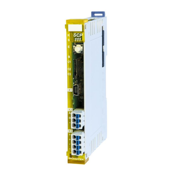
- Page 3 S-DIAS SAFETY CPU MODULE SCP 111 S-DIAS Safety CPU Module E SCP 111 The S-DIAS Safety CPU module supports up to 16 Safe IO modules. In addition, the SCP 111 can operate handheld devices with Emergency Stop and/or confirmation buttons. The Safety CPU component has the safety integrity level SIL3 or SIL CL 3 (EN / IEC 62061) or Performancelevel e (PL e) (EN ISO 13849-1/-2).
-
Page 4: Table Of Contents
SCP 111 S-DIAS SAFETY CPU MODULE Contents Basic Safety Guidelines ............4 General Safety Information ............4 Further Safety Guidelines ............5 General Requirements ..............6 Safety Conformity ..............10 Functional Safety Standards ............. 10 EU Conformity Declaration ............10 Safety-Relevant Parameters ............10 Compatibility ................ - Page 5 S-DIAS SAFETY CPU MODULE SCP 111 Validation Button ..............22 Explanation of the Individual Sequences ......... 22 6.1.1 Start Sequence ................. 22 6.1.2 Command Selection Sequence ............23 6.1.3 End Sequence .................. 23 6.1.4 Error Sequence ................. 24 Overview of Commands ............. 25 Overview of Module Status and Commands ......
-
Page 6: Basic Safety Guidelines
SCP 111 S-DIAS SAFETY CPU MODULE Basic Safety Guidelines General Safety Information If the safety guidelines are not followed, danger to personnel can arise that could lead to serious injury or in worst cases, death. In less serious cases, systems and equipment can be damaged. -
Page 7: Further Safety Guidelines
S-DIAS SAFETY CPU MODULE SCP 111 Further Safety Guidelines Warning, dangerous electrical voltage Avertissement d’une tension électrique dangereuse Hot surface warning Avertissement d’une surface chaude Danger for ESD-sensitive components This symbol identifies important additional information regarding the operation of the safety modules. -
Page 8: General Requirements
Before handling the product to which this documentation Guidelines belongs, the operating instructions and safety guidelines must be read. SIGMATEK GmbH & Co KG accepts no liability for damages resulting from non-compliance with the safety guidelines or the relevant regulations... - Page 9 S-DIAS SAFETY CPU MODULE SCP 111 Qualified Personnel Installation, assembly, programming initial start-up, operation, maintenance and decommissioning of control and automation technology products in general, as well as safety- related products especially, can only be performed by qualified personnel. Qualified personnel in this context are people, who have completed training or have trained under supervision of qualified personnel and have been authorized to operate and maintain safety-related equipment, systems and facilities in...
- Page 10 SCP 111 S-DIAS SAFETY CPU MODULE Designated Use The Safety modules are designed for use in safety-oriented applications and meet the required conditions for safety operation in compliance with Performancelevel e (PL e), in accordance with EN ISO 13849-1/-2 and SIL3 or SIL CL 3 in accordance with EN 62061.
- Page 11 S-DIAS SAFETY CPU MODULE SCP 111 Operator Due Diligence The operator must ensure that • the Safety modules are to be used for their designated purpose only. • the Safety modules are to be operated in error-free, fully functional condition only. •...
-
Page 12: Safety Conformity
• 2011/65/EU Restricted use of certain hazardous substances in electrical and electronic equipment (RoHS Guideline) The EU Conformity Declarations are provided on the SIGMATEK website. Using the search function with the keyword “EU Declaration of Conformity”. Safety-Relevant Parameters CPU Module... -
Page 13: Compatibility
S-DIAS SAFETY CPU MODULE SCP 111 Compatibility The safety-related component, SCP 111, is supported with Firmware version 423 or Build No, 1348 and higher of the Safety Designer. Compatibility In regard to compatibility with the S-DIAS Safety component, section "Compatibility with S-DIAS Safety Components" in the system handbook is referenced. -
Page 14: Technical Data
SCP 111 S-DIAS SAFETY CPU MODULE Technical Data Performance Data Interfaces 1x Safety Interface Program interfaces 1x USB device Bus connection possible Miscellaneous microSD slot Supply voltage +24 V Electrical Requirements 3.2.1 Module Supply (Input) Supply voltage +18-30 V DC, typically +24 V DC UL: Class 2 or LVLC Current, internal consumption typically 90 mA internal consumption... -
Page 15: S-Dias Bus/Safety Supply (Output)
S-DIAS SAFETY CPU MODULE SCP 111 3.2.2 S-DIAS Bus/Safety Supply (Output) Voltage supply in the +5 V +24 V S-DIAS bus in the +12 V +24 V S-DIAS Safety bus (2) (4) (2) (4) max. 0,8 A max. 0,8 A (supply of the I/O modules) ______________ For USA and Canada:... - Page 16 SCP 111 S-DIAS SAFETY CPU MODULE If the SCP 111 with a firmware version lower than V431 resp. with a Safety number lower than S01.03.01 is integrated with Safety I/O modules in the S-DIAS system (blue moduls), the voltage increase of the +24 V supply of the SCP 111 must not happen later than 100 msec after the voltage supply oft he S-DIAS supply moduls, otherwise it can happen, that the SCP 111 does not recognize the Safety I/O moduls on the Safety bus.
- Page 17 S-DIAS SAFETY CPU MODULE SCP 111 28.02.2020 Page 15...
-
Page 18: Miscellaneous
SCP 111 S-DIAS SAFETY CPU MODULE Miscellaneous Article number 20-890-111 Hardware version Standard UL 508 (E247993) Approbations UL, cUL, CE Environmental Conditions Storage temperature -20 ... +85 °C Environmental temperature 0 ... +55 °C Humidity 0-95 %, non-condensing Installation altitude above sea 0-2000 m without derating level >... -
Page 19: Mechanical Dimensions
S-DIAS SAFETY CPU MODULE SCP 111 Mechanical Dimensions 28.02.2020 Page 17... -
Page 20: Connector Layout
SCP 111 S-DIAS SAFETY CPU MODULE Connector Layout The connections of the +24 V supply (X3: pin 1 and pin 2) or the GND supply (X3: pin 3 and pin 4) are internally bridged. To supply the module, only one connection to a +24 V pin (pin 1 or pin 2) and a GND pin (pin 3 or pin 4) is required. -
Page 21: Status Leds
S-DIAS SAFETY CPU MODULE SCP 111 Status LEDs The LED display lights continuously to indicate that the in- and outputs are active. green Indicates The time-limited (LED "S" on) operation mode or Or unlimited time ("S" LED off) operation mode. Module yellow status... -
Page 22: Applicable Connectors
SCP 111 S-DIAS SAFETY CPU MODULE Applicable Connectors Connectors: X1: USB Type Mini-B (not included in delivery) X2 – X3: Connectors with spring terminals (included in delivery) The spring terminals are suitable connecting ultrasonically compacted (ultrasonically welded) strands. Connections: Stripping length/Sleeve length: 10 mm Mating direction: parallel to the lead axis or circuit board... -
Page 23: Label Field
S-DIAS SAFETY CPU MODULE SCP 111 Label Field Manufacturer Weidmüller Type MF 10/5 CABUR MC NE WS Weidmüller article number 1854510000 Compatible printer Weidmüller Type Printjet Advanced 230V Weidmüller article number 1324380000 28.02.2020 Page 21... -
Page 24: Validation Button
SCP 111 S-DIAS SAFETY CPU MODULE Validation Button With the validation button S1, several commands as well as the validation can be executed: • Acknowledging an error and exiting the error status • Deleting a configuration from the Safety CPU •... -
Page 25: Command Selection Sequence
S-DIAS SAFETY CPU MODULE SCP 111 6.1.2 Command Selection Sequence After the Start sequence, the desired command is selected. This selection is made with button presses in the following time intervals: Minimum press duration is 200 ms, maximum is approximately 3 seconds; the minimum pause between individual button presses is 200 ms, the maximum is 10 seconds. -
Page 26: Error Sequence
SCP 111 S-DIAS SAFETY CPU MODULE 6.1.4 Error Sequence If an invalid button press occurs, as in the sequences described above, the Error sequence is initiated. LED B indicates this sequence with fast blinking, which lasts for at least 3 seconds. -
Page 27: Overview Of Commands
S-DIAS SAFETY CPU MODULE SCP 111 Overview of Commands The number of button presses corresponds to the number of light pulses in LED B during the End sequence. Commands Number of button LED C1 LED C2 LED C3 presses QUIT_ERROR CLR_CFG SET_VERIFIED Overview of Module Status and Commands... - Page 28 SCP 111 S-DIAS SAFETY CPU MODULE Executed Command function Status after command execution command QUIT_ERROR A possible error is cancelled in the Safety CPU SW-RESET *) and all safety modules required by the Safety CPU and the error status is ended. CLR_CFG The configuration in the Safety CPU is deleted.
-
Page 29: Handling The Microsd Card
Safety System Handbook (Link: https://www.sigmatek- automation.com/fileadmin/user_upload/downloads/Safety-Systemhandbuch-eng.pdf). A Safety project, which was programmed with the SafetyDesigner, can be stored on an SD card. The stored Safety project can then be loaded into an additional SCP Safety-CPU, providing that the module's Flash memory is empty (cleared). -
Page 30: Configuring A Safety Cpu With The Sd Card
Only microSD cards that support version 2.0 or higher of the "SDA Physical Layer Specification" (SDA=SD Card Association) can be used. It is recommended to use only the microSD card approved by SIGMATEK. The number of read and write accesses has a significant influence on the service life of the storage medium. - Page 31 SCP 111 Une carte microSD d'une capacité de stockage de 1 Go est disponible chez SIGMATEK sous le numéro d’article 12-630-101. Uniquement les cartes microSD supportant au moins la version 2.0 de la "SDA Spécification de la couche physique" (SDA = SD Card Association) peuvent être utilisées.
-
Page 32: Error Response
SCP 111 S-DIAS SAFETY CPU MODULE Error Response In the event of an error, please consult the chapter "LED Displays", as important information on the runtime status of the system can be derived from the status an error display. Since errors in general are of a complex nature, do not perform a diagnosis based on the LEDs alone (consult the corresponding chapter in the Safety System Handbook as well). -
Page 33: Configuration Distribution Error
S-DIAS SAFETY CPU MODULE SCP 111 During restart, the Safety CPU first runs the POST (Power On Self Test). In the POST, whether the Safety CPU is configured or not is determined. If the Flash memory in the Safety CPU is empty, it changes to the service mode and switches the status LED (ST) to continuously on. -
Page 34: Troubleshooting
SCP 111 S-DIAS SAFETY CPU MODULE Troubleshooting • Check all modules in the system for completeness and Type conformity • Check that all modules are error-free • Check all connector cables • Cancel the error with the QUIT_ERROR command If the Safety CPU remains in the error status after the QUIT_ERROR command has been executed, it must be retested using the SafetyDesigner. -
Page 35: Wiring Guidelines
S-DIAS SAFETY CPU MODULE SCP 111 Wiring Guidelines The input filters, which suppress noise signals, allow operation in harsh environmental conditions. A careful wiring method is also recommended to ensure error-free function. The following installation guidelines should be observed: • Avoid parallel connections between input lines and load-bearing circuits. -
Page 36: Mounting
SCP 111 S-DIAS SAFETY CPU MODULE Mounting The S-DIAS modules are designed for installation into the control cabinet. To mount the modules a DIN-rail is required. The DIN rail must establish a conductive connection with the back wall of the control cabinet. The individual S-DIAS modules are mounted on the DIN rail as a block and secured with latches. - Page 37 S-DIAS SAFETY CPU MODULE SCP 111 Recommended minimum distances of the S-DIAS modules to the surrounding components or control cabinet wall: a, b, c … distances in mm (inches) 28.02.2020 Page 35...
-
Page 38: 10 Supported Cycle Times
SCP 111 S-DIAS SAFETY CPU MODULE 10 Supported Cycle Times 10.1 Cycle Times below 1 ms (in µs) x= supported 10.2 Cycle Times equal to or higher than 1 ms (in ms) x= supported x= supported 11 Disposal For the disposal of the product, the respective guidelines, possibly country-specific, must be observed and followed. - Page 39 S-DIAS SAFETY CPU MODULE SCP 111 Documentation Changes Change date Affected Chapter Note page(s) 08.07.2015 3.2 Electrical Requirements Added note 04.08.2015 Info Cover Translation from German added 15.10.2015 11, 12 3.2 Electrical Requirements Table split 20.01.2016 3.2 Electrical Requirements updated 21.01.2016 3.3 Miscellaneous Standard changed...
- Page 40 SCP 111 S-DIAS SAFETY CPU MODULE Page 38 28.02.2020...
Need help?
Do you have a question about the S-DIAS SCP 111 and is the answer not in the manual?
Questions and answers