Table of Contents
Advertisement
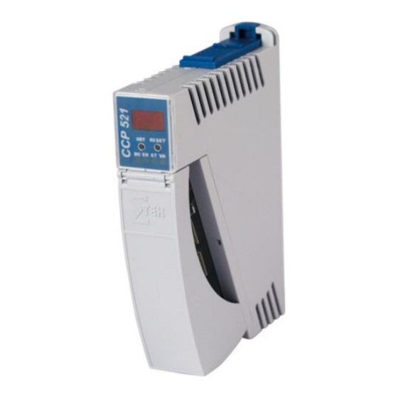
C-DIAS PROCESSOR MODULE
CCP 521
C-DIAS Processor Module
CCP 521
The CCP 521 processor module runs the control program and
thereby represents an essential component of an automation sys-
tem. The internal DC/DC converter powers all modules on a
C-DIAS module carrier.
The CAN bus, an Ethernet interface or the USB device (Mini USB)
can be used as the online interface.
A 7-segment display and 2 status LEDs provide information on the
actual status of the CPU.
For program updates, the integrated USB Host interface can be
used (USB stick, keyboard). With help from the exchangeable SD
card, the entire control program can be easily exchanged.
The CCP 521 processor module is designed to be mounted in the
control cabinet.
With the integrated VARAN manager, the processor module offers the possibility to con-
struct a high-performance VARAN system to operate for example, decentralized I/O mod-
ules, drive systems or communication modules.
Compatibility
Completely PC-compatible. The CCP 521 works with standard PC BIOS and therefore no
SIGMATEK-specific BIOS is needed; the LASAL operating system in provided.
15.03.2016
Page 1
Advertisement
Table of Contents

Related Manuals for SIGMATEK CCP 521


Summary of Contents for SIGMATEK CCP 521
- Page 1 VARAN system to operate for example, decentralized I/O mod- ules, drive systems or communication modules. Compatibility Completely PC-compatible. The CCP 521 works with standard PC BIOS and therefore no SIGMATEK-specific BIOS is needed; the LASAL operating system in provided. 15.03.2016...
-
Page 2: Technical Data
CCP 521 C-DIAS PROCESSOR MODULE Technical Data Performance data Processor EDGE-Technology X86 compatible 16-bit data bus Clock frequency 500 MHz Addressable I/O/P modules VARAN bus: 65.280 CAN bus: 32 C-DIAS bus: 8 Internal I/O Internal cache 32-kbyte L1 Cache 256-kbyte L2 Cache... - Page 3 En configurant d’une façon appropriée le filtre de paquets (pare-feu ou un routeur) il est toutefois possible de connecter un réseau avec le matériel SIGMATEK à un réseau tiers sans déclencher l'erreur mentionnée ci-dessus.
-
Page 4: Environmental Conditions
CCP 521 C-DIAS PROCESSOR MODULE Miscellaneous Article number 12-104-521 Hardware version Project back-up Internally on the microSD card Standard UL508 (E247993) Environmental conditions Storage temperature -10 ... +85 °C Operating temperature 0 ... +60 °C Humidity 10 - 90 %, uncondensed... -
Page 5: Mechanical Dimensions
C-DIAS PROCESSOR MODULE CCP 521 Mechanical Dimensions 24.90 15.03.2016 Page 5... -
Page 6: Connector Layout
CCP 521 C-DIAS PROCESSOR MODULE Connector Layout Page 6 15.03.2016... - Page 7 C-DIAS PROCESSOR MODULE CCP 521 X1: USB Device 1.1 Function +5 V X2: USB Host 2.0 Function +5 V It should be noted that many of the USB devices on the market do not comply with USB specifications; this can lead to device malfunctions. It is also possible that these devices will not be detected at the USB port or function correctly.
- Page 8 CCP 521 C-DIAS PROCESSOR MODULE X4: VARAN-Out Function TX+ / RX+ TX- / RX- RX+ / TX+ 4 - 5 RX- / TX- 7 - 8 More information on the VARAN bus can be found in the VARAN bus specifica-...
- Page 9 +3V3 DAT0 DAT1 It is recommended that only storage media provided by SIGMATEK (CompactFlash cards, microSD cards etc.) be used. Order number for the 512-Mbyte EDGE microSD card: 12-630-051 The number of read and write actions have a significant influence on the lifespan of the storage media.
- Page 10 CCP 521 C-DIAS PROCESSOR MODULE Exchanging the microSD card The microSD card is located under the LED cover. To exchange the microSD card, carefully lift the LED cover. The microSD card is located on the left side and can be disengaged by lightly pressing on the card itself.
- Page 11 2-pin Phoenix plug with screw terminal technology MC 1.5/ 2-ST-3.5 2-pin Phoenix plug with spring terminal FK-MCP 1.5/ 2-ST-3.5 The complete C-DIAS CKL 017 connector set with spring terminals is available from Sigmatek under the article number 12-600-017. 15.03.2016 Page 11...
-
Page 12: Status Displays
CCP 521 C-DIAS PROCESSOR MODULE Status Displays Ethernet Color Description Active Yellow Lights when data is exchanged over Ethernet Link Green Lights when the connection between the two PHYs is established VARAN Color Description Active Yellow Lights when data is exchanged over the VARAN bus... - Page 13 C-DIAS PROCESSOR MODULE CCP 521 Display The CCP 521 processor module has a 2-digit decimal display (7 segment display) for the following functions: When configuring the processor module, the parameters are shown in the display. If an error occurs while running the program or no valid user program is found, the dis- play shows an error message.
-
Page 14: Can Bus Setup
CCP 521 C-DIAS PROCESSOR MODULE CAN Bus Setup This section explains how to configure a CAN bus correctly. The following parameters must first be set: Station number and data transfer rate. CAN bus station number Each CAN bus station is assigned its own station number. With this station number, data can be exchanged with other stations connected to the bus. - Page 15 C-DIAS PROCESSOR MODULE CCP 521 Configuration of the Process Module 15.03.2016 Page 15...
- Page 16 CCP 521 C-DIAS PROCESSOR MODULE To enter the mode for setting changes, press and hold the SET button while the C-IPC is booting. When the following appears in the display: the SET button can be released. After releasing the SET button, the first menu appears in the display.
- Page 17 C-DIAS PROCESSOR MODULE CCP 521 ... CAN PLC station 00 – 30 ... Station number C2 ... CAN PLC baud rate 00 ... 615.000 01 … 500.000 02 … 250.000 03 … 125.000 04 … 100.000 05 … 50.000 06 … 20.000 07 …...
-
Page 18: Can Bus Termination
CAN-Bus-Connections If the CCP 521 processor module is an end module, it can be terminated by placing a 150- Ohm resistor between CAN-A (Low) and CAN-B (High). 1 x 150-Ohm resistor Page 18 15.03.2016... -
Page 19: Earth Connection
Wiring and Mounting Instructions Earth Connection The CCP 521 must be connected to earth over the mounting on the back wall of the control cabinet or over the earth terminal provided (C-DIAS module carrier). It is important to cre- ate a low-ohm earth connection, only then can error-free operation be guaranteed. The earth connection should have the maximum cross section and the largest electrical surface possible. -
Page 20: Esd Protection
ESD Protection Before any device is connected to or disconnected from the CCP 521, the potential with ground should be equalized (by touching the control cabinet or earth terminal). Static elec- tricity (from clothing, footwear) can therefore be reduced. -
Page 21: Process Diagram
C-DIAS PROCESSOR MODULE CCP 521 Process Diagram 15.03.2016 Page 21... - Page 22 CCP 521 C-DIAS PROCESSOR MODULE System Boot Checkpoints The checkpoints are shown on the 7-segment display before the LASAL CLASS software status and error messages. Since this involves checkpoints, it should be interpreted as errors when the system stops at a checkpoint.
-
Page 23: Status And Error Messages
C-DIAS PROCESSOR MODULE CCP 521 Status and Error Messages Status and error messages are shown in the status test of the LASAL CLASS software. If the CPU has a status display, the status or error number is also show here as well. - Page 24 CCP 521 C-DIAS PROCESSOR MODULE Watchdog The program was interrupted through Possible Causes: the watchdog logic. Interrupts blocked by the user program for an extensive period of time (STI instruction forgotten). Programming error in a hardware interrupt. INB, OUTB, INW, OUTW instructions used incorrectly.
- Page 25 C-DIAS PROCESSOR MODULE CCP 521 PROG MEMO The CPU is currently programming the memory module. STOP BRKPT The CPU was stopped by a breakpoint in the program. CPU STOP The CPU was stopped by the PG soft- ware (F6 HALT in status test).
- Page 26 CCP 521 C-DIAS PROCESSOR MODULE DIAS ERROR An error has occurred while ac- Possible Causes: cessing a DIAS module. An attempt is made to access a nonexistent DIAS module. DIAS bus error. Solution: Check the DIAS bus Check the termination resistors.
- Page 27 C-DIAS PROCESSOR MODULE CCP 521 VARAN MANAGER ERROR In the VARAN Manager, an error Possible causes: number was stored and the pro- Real network does not match gram execution was stopped. the project Solution: Read log file VARAN ERROR A required VARAN Client was...
- Page 28 CCP 521 C-DIAS PROCESSOR MODULE BACKGROUND RUNTIME The total time for all background objects exceed the maximum time; the time can be configured using two system varia- bles: BTRuntime: time remaining SWBTRuntime: pre-selected value for the runtime counter C-DIAS ERROR...
- Page 29 C-DIAS PROCESSOR MODULE CCP 521 C_RUNRAM The LASAL project was successfully started from RAM. C_RUNROM The LASAL project was successfully started from ROM. C_RUNTIME C_READY The CPU is ready for operation. C_OK The CPU is ready for operation. C_UNKNOWN_CID An unknown class from a stand-along or embedded object: unknown base class.
- Page 30 CCP 521 C-DIAS PROCESSOR MODULE OP BURN FAIL An error has occurred while burning the operating system. OP INSTALL The operating system is currently being installed. USV-WAIT The power supply was disconnected; the UPS is active. Reboot The operating system is restarted.
- Page 31 C-DIAS PROCESSOR MODULE CCP 521 Application exceptions SRAM and IRQ routines Writing remnant data during interrupt routines is not allowed and leads to a system crash. SRAM and consistency of changed data If more than 32 different sectors are changed (512 bytes each) shortly before shutting down the voltage supply while the user program is writing to the microSD card, this can sometimes lead to partial loss of remnant data.
- Page 32 CCP 521 C-DIAS PROCESSOR MODULE Note on SRAM Behavior Because the SRAM (remnant memory) is emulated via the microSD card, there are two different mechanisms for saving SRAM data to the microSD card: 1. Cyclic writing when data is changed (default) 2.
- Page 33 It is recommended to avoid placing VARAN bus lines parallel to power cables whenever possible. SIGMATEK recommends the use of CAT5e industrial Ethernet bus cables. For the shielding, an S-FTP cable should be used. An S-FTP bus is a symmetric, multi-wire cable with unshielded pairs. For the total shield- ing, a combination of foil and braiding is used.
- Page 34 CCP 521 C-DIAS PROCESSOR MODULE 1. Wiring from the Control Cabinet to an External VARAN Com- ponent If the Ethernet lines are connected from a VARAN component to a VARAN node located outside the control cabinet, the shielding should be placed at the entry point to the control cabinet housing.
-
Page 35: Wiring Outside Of The Control Cabinet
C-DIAS PROCESSOR MODULE CCP 521 2. Wiring Outside of the Control Cabinet If a VARAN bus cable must be placed outside of the control cabinet only, no additional shield connection is required. This requires that only IP67 modules and connectors be used. - Page 36 CCP 521 C-DIAS PROCESSOR MODULE 3. Shielding for Wiring Within the Control Cabinet Sources of strong electromagnetic noise located within the control cabinet (drives, Trans- formers, etc.) can induce interference in a VARAN bus line. Voltage spikes are dissipated over the metallic housing of a RJ45 connector. Noise is conducted over the control cabinet without additional measures needed on the circuit board of electronic components.
- Page 37 C-DIAS PROCESSOR MODULE CCP 521 4. Connecting Noise-Generating Components When connecting power lines to the bus that generate strong electromagnetic noise, the correct shielding is also important. The shielding should be placed before a power element (or group of power elements).
- Page 38 CCP 521 C-DIAS PROCESSOR MODULE 5. Shielding Between Two Control Cabinets If two control cabinets must be connected over a VARAN bus, it is recommended that the shielding be located at the entry points of each cabinet. Noise is therefore prevented from reaching the electronic components in both cabinets.
Need help?
Do you have a question about the CCP 521 and is the answer not in the manual?
Questions and answers