
Subscribe to Our Youtube Channel
Related Manuals for Still EXV 10 Basic


Summary of Contents for Still EXV 10 Basic
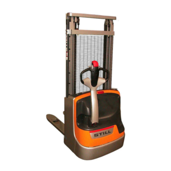
- Page 1 Original instructions Pallet stacker EXV 10 Basic EXV 10 / 10i EXV 12 / 12i EXV 14C / 14iC 45728043478 EN - 11/2021 - 09...
- Page 3 Internet address and QR code The information can be accessed at any time by pasting the address https://m.still.de/vdma in a web browser or by scanning the QR code. 45728043478 EN - 11/2021 - 09...
- Page 5 Preface Address of manufacturer and contact details STILL GmbH Berzeliusstraße 10 22113 Hamburg, Germany Tel. +49 (0) 40 7339-0 Fax: +49 (0) 40 7339-1622 Email: info@still.de Website: http://www.still.de 45728043478 EN - 11/2021 - 09...
-
Page 7: Table Of Contents
Table of contents Introduction Forklift data ............General information . - Page 8 Table of contents Vibrations............Safety tests .
- Page 9 Table of contents Transporting and lifting the truck ......... Transporting the truck .
- Page 10 Datasheet (VDI) EXV 10 Basic and EXV 10 ....... .
-
Page 11: Introduction
Introduction... -
Page 12: Forklift Data
Introduction Forklift data Forklift data We recommend that you record the principal forklift data in the following table so that they are available if required by the sales network or authorised service centre. Type Serial number Date of delivery General information This manual contains "Original Instructions"... - Page 13 Introduction How to Consult the Manual ENVIRONMENT NOTE NOTE This symbol is used to provide additional infor- Failure to observe the instructions highlighted mation. with this symbol may cause environmental damage. 45728043478 EN - 11/2021 - 09...
-
Page 14: Date Of Edition And Latest Update Of This Manual
Introduction Date of edition and latest update of this manual Date of edition and latest up- date of this manual The publication date of these operating in- structions is printed on the cover sheet. The manufacturer makes continuous efforts to improve its industrial trucks, and therefore re- serves the right to implement changes and to accept no claims concerning the information... -
Page 15: Spare Parts List
You can request to download the spare parts list by copying and pasting the address https:// sparepartlist.still.eu into a web browser or by scanning the QR code shown to the side. On the web page, enter the following pass-... -
Page 16: Declaration That Reflects The Content Of The Declaration Of Conformity
Declaration that reflects the content of the declaration of conformity Declaration that reflects the content of the declaration of con- formity Declaration STILL GmbH Berzeliusstraße 10 22113 Hamburg Germany We declare that the specified machine conforms to the most recent valid version of the direc-... - Page 17 Introduction Declaration that reflects the content of the declaration of conformity handed over to the new owner if the industrial truck is sold on. 45728043478 EN - 11/2021 - 09...
-
Page 18: Technical Service And Spare Parts
Introduction Technical service and spare parts Technical service and spare parts For scheduled maintenance and any repairs to the technical characteristics of the forklift over the forklift, contact only the authorised service time. network. Only original spare parts provided by the man- The authorised service network has personnel ufacturer may be used for forklift maintenance trained by the manufacturer, original spare... -
Page 19: Working Conditions
Introduction Working conditions Working conditions The truck must not be used outside the climat- The truck has been designed and built for in- ic conditions indicated below: ternal transport. Maximum ambient temperature: +40°C ● Minimum ambient temperature: +5°C ● Altitude up to 2000 m ●... -
Page 20: Modifications To Forklift
Introduction Modifications to Forklift Modifications to Forklift No modifications may be made to the forklift, DANGER otherwise the EC certificate and the warranty If the forklift is equipped at the factory or later with will become invalid, with the exception of: devices that emit non-ionising radiation (such as ra- Assembly of the options, only if provided by dio transmitters, RFID players, data terminals,... -
Page 21: Environmental Considerations
Introduction Environmental considerations Environmental considerations Disposal of components and batteries The truck is composed of different materials. If components or batteries need to be replaced and disposed of, they must be: disposed of, ● treated or ● recycled in accordance with regional and ●... -
Page 22: Packaging
Introduction Environmental considerations Packaging During delivery of the truck, certain parts are packaged to provide protection during trans- port. This packaging must be removed com- pletely prior to initial start-up. ENVIRONMENT NOTE The packaging material must be disposed of properly after delivery of the truck. 45728043478 EN - 11/2021 - 09... -
Page 23: Safety
Safety... -
Page 24: Safety Guidelines
Safety Safety guidelines Safety guidelines General Precautions lations integrate those in the manual "Rules NOTE for approved use of industrial vehicles". Some safety regulations to be followed when using the forklift are listed below. These regu- General Safety Rules Only allow qualified, trained and authorized load is as close as possible to the fork car- ●... -
Page 25: Battery Connection Cables
Safety Safety guidelines are met. For this reason, the manufacturer cannot be CAUTION held liable for any damage to the truck (especially to wheels, hubs etc.) caused by use on unsuitable sur- Passing over cracks or damaged parts of the floor faces. -
Page 26: Safety Guidelines Relating To Operating Materials
Safety Safety guidelines Safety guidelines relating to operating materials Rules for handling and disposing of op- ENVIRONMENT NOTE erating materials The used oils and relative filters contain sub- stances that are hazardous to the environment ENVIRONMENT NOTE and they must be disposed of according to Improper use and disposal of operating and current regulations. - Page 27 Safety Safety guidelines be carried out as required by law. We advise ENVIRONMENT NOTE you to contact the authorised service network that is equipped for eco-friendly disposal in The batteries contain substances that are haz- accordance with current regulations. ardous to the environment. The replacement and disposal of the life-expired battery must 45728043478 EN - 11/2021 - 09...
-
Page 28: Residual Risk
Safety Residual risk Residual risk Residual dangers, residual risks Despite careful use and compliance with standards and regulations, the possibility of other risks occurring when using the truck cannot be entirely excluded. The truck and all other system components comply with current safety requirements. Nev- ertheless, even when the truck is used for its proper purpose and all instructions are fol- lowed, some residual risks cannot be exclu-... -
Page 29: Electromagnetic Radiation
Safety Electromagnetic radiation with these regulations either intentionally or due to negligence. Stability The stability of the truck has been tested in accordance with up-to-date technical regula- tions and is guaranteed if the truck is used correctly and in line with the intended purpose. These standards only take into account the static and dynamic tipping forces that can arise during use in accordance with the oper-... -
Page 30: Non-Ionised Radiation
Safety Non-ionised radiation malfunctioning or for any injuries and/or dam- result of modifications made to the original age inflicted on objects and/or persons as a product ex-works. Non-ionised radiation If the truck is equipped at the factory or later of such devices must be verified with the pres- with devices that emit non-ionising radiation ence of operators using medical devices (such (such as radio transmitters, RFID players, da-... -
Page 31: Vibrations
Safety Vibrations Vibrations Vibrations to which the hands and arms CAUTION are exposed The value expressed above can be used to compare forklift trucks of the same category. It cannot be used The following value is valid for all truck mod- to determine the operator's daily exposure to vibra- els: tions during real operation of the truck;... -
Page 32: Safety Tests
Safety tests Regular safety inspection of the truck Safety inspection based on time and ex- STILL GmbH Hamburg traordinary incidents Regelmäßige Prüfung The operating company must ensure that the (FEM 4.004) truck is checked at least once a year, or fol- nach nationalen Vorschriften lowing noteworthy incidents. -
Page 33: Safety Devices
Safety Safety devices Safety devices Location of safety devices Main safety devices on the truck The operator must be aware of the following Horn safety devices: Electromagnetic brake Guard grille Truck braking when the tiller arm reaches Anti-crush safety feature the upper end position and lower end posi- Braking by releasing the drive control throttle tion. -
Page 34: Damage, Defects And Misuse Of Safety Devices
Safety Safety devices Damage, defects and misuse of safety devices The driver must report any damage or other defects to the truck or attachment immediately to the supervisory personnel. Trucks and attachments that are not functional or safe may not be used until they have been properly repaired. -
Page 35: Overview
Overview... -
Page 36: Technical Description
Overview Technical description Technical description EXV10 Basic and EXV10: 1000 kg EXV10 Basic, EXV10, EXV12 and EXV12 i, ● EXV14C and EXV14iC trucks are designed to EXV12 and EXV12 i: 1200 kg ● handle and stack pallets with a maximum EXV14C and EXV14iC: 1400 kg ●... - Page 37 Overview Technical description Driving counter-current, controlled by the anti-crush ● safety button A long, robust and ergonomic tiller arm allows Electromagnetic safety, controlled by the ● the operator to drive the truck easily. emergency stop handle safety electromagnetic, controlled by the re- The tiller is used to carry out the following con- ●...
-
Page 38: Overviews
Overview Overviews Overviews 0252_003-066 Mast Stabiliser wheel Lift chains Traction wheel Protective screen Gearbox Tiller Traction motor Emergency isolator button Brake Fuse carrier Forks Battery connector Load wheels Built-in battery charger (if present) Electronic panel Pump motor Battery Hydraulic oil reservoir Lift cylinder 45728043478 EN - 11/2021 - 09... -
Page 39: Instruments And Controls
Overview Instruments and controls Instruments and controls Tiller controls 1 — Tiller head handle 2 and 3 — Drive control throttle 4 — Fork lowering button 5 — Fork lifting button 6 — Horn button 7 — Anti-crush button 8 —... - Page 40 Overview Instruments and controls NOTE The speed of the forks is proportional to how hard the button (5) is pressed Horn button (6) Press the button (6) to operate the horn ● This device allows the driver to signal his presence when necessary Anti-crush button (7) Press the button (7) while the truck is travel-...
- Page 41 Overview Instruments and controls WARNING Risk of crushing feet. Be careful not to put your feet under the straddles while using the initial lift function. Straddle lifting button (9) Press the button (9) to lift the straddles; ● when the button is released, the straddles will stop in the position reached The straddle lifting button (9) is active only ●...
-
Page 42: Display
Overview Instruments and controls Display (1) Battery charge level indicator The indi- (4) Green indicator light ● ● cator operates after the battery connector Switched off: truck switched off has been connected. Monitoring the dis- Switched on: truck switched on charge process protects the battery against (5) Malfunction code deep discharge. - Page 43 Overview Instruments and controls When the power supply is disconnected, (9) Temperature alarm (red) ● the hours are stored in the memory. Cool down the truck. If the problem persists, (8) STOP alarm (red) contact the technical service centre. ● Various types of problem.
-
Page 44: Controls For Switching On And Switching Off
Overview Instruments and controls Controls for switching on and switching off Switching on and switching off are performed using: the key switch (standard version) ● or the numeric keypad "Digicode" (optional ● version) Standard version with key On the standard version, the key has three po- sitions: “0”... -
Page 45: Emergency Stop Handle
Overview Instruments and controls Emergency stop handle – Pressing the emergency stop handle (1) will lock all the functions on the truck. – To restore the operating conditions, elimi- nate the causes of the emergency, then re- lease the tiller in the rest position and un- lock the emergency stop handle by lifting it. -
Page 46: Tiller Positions
Overview Instruments and controls Tiller positions Position the tiller in accordance with the truck functions With the truck stopped, the two following tiller positions are available: Position (1) = working position. ● In this position, the operator can begin trav- el using the throttle. - Page 47 Overview Instruments and controls “Timone sempre attivo” version (option- al — Creep Speed) Position (2) using the "tiller always active" ● function (optional) = creep speed position This function is activated by pressing the creep speed button on the tiller (3) and ro- tating the drive control throttle (4) or by pressing the creep speed button and the fork lifting button.
-
Page 48: Tiller Controls
Overview Tiller controls Tiller controls 1 — Tiller head handle 2 and 3 — Drive control throttle 4 — Fork lowering button 5 — Fork lifting button 6 — Horn button 7 — Anti-crush button 8 — Creep Speed button (optional) 9 —... - Page 49 Overview Tiller controls NOTE The speed of the forks is proportional to how hard the button (5) is pressed Horn button (6) Press the button (6) to operate the horn ● This device allows the driver to signal his presence when necessary Anti-crush button (7) Press the button (7) while the truck is travel- ●...
-
Page 50: Optispeed Tiller (If Present)
Overview OptiSpeed tiller (if present) WARNING Risk of crushing feet. Be careful not to put your feet under the straddles while using the initial lift function. Straddle lifting button (9) Press the button (9) to lift the straddles; ● when the button is released, the straddles will stop in the position reached The straddle lifting button (9) is active only ●... -
Page 51: Types Of Lifting Masts
Overview Types of lifting masts Types of lifting masts Your truck may be fitted with one of the follow- ing masts: Simplex ● Telescopic ● NiHo ● Triplex ● Simplex When the "lift" button is pressed, the fork car- riage is raised to the height h3 by the central cylinder via a chain. - Page 52 Overview Types of lifting masts CAUTION In locations with a low ceiling, be aware that the load height may be greater than the mast height. Triplex The function is identical to that of the NiHo mast, but has a greater lift height with the same mast height.
-
Page 53: Definition Of Directions
Overview Definition of directions Definition of directions Direction of movement defined by the regula- tions: Forward travel (1) (preferred direction of ● travel) Right (2) ● Reverse travel (3) ● Left (4) ● 0252_003-008 45728043478 EN - 11/2021 - 09... -
Page 54: Markings
Overview Markings Markings Location of labels Pb+Sb 2342 "Truck capacity diagram" label Version set up for gel batteries "Danger of crushing hands" label "On-board battery charger" label "Hook" symbol Annual testing label (Germany only) "Danger of crushing hands" label Warning label "Operating and maintenance manual"... -
Page 55: Serial Number
Overview Markings Description of labels (7) This label indicates that you should consult the specific operating and maintenance man- (1) This label indicates the permissible load on ual for the on-board battery charger. the forks depending on load centre of gravity (8) This symbol, where present, indicates that and lift height. -
Page 56: Nominal Value Designation Plate
Overview Markings Nominal value designation plate DANGER Danger! To avoid compromising the stability of the truck, it is strictly forbidden to use batteries that weigh less than the minimum weight (11) indicated on the designation plate. NOTE Please indicate the serial number for all ●... -
Page 57: Capacity Plate
Overview Markings Capacity plate – The identification plate indicates the follow- ing data: (1) CDG = distance "C" from the centre of ● gravity of the load on the forks to the fork carriage (in mm) (2) h = lift height of the forks from the ●... -
Page 58: Chassis Frame Labelling
Overview Markings Chassis frame labelling 2274 The truck's serial number is marked on the chassis frame . The serial number is located in the following places: A for standard versions of the truck ● B for models with initial lift capability ●... -
Page 59: Options And Variants
Overview Options and variants Options and variants List of optional fittings List: Forks of various gauges ● Load backrest, height 1000 mm ● Various types of tyre for the drive wheel ● Guard plate in transparent polycarbonate ● Access authorisation via Digicodesystem ●... -
Page 60: Numeric Keypad - Start-Up Using A Pin (Option)
Overview Options and variants Numeric keypad — Start-up using a PIN (option) SWITCH ON (operating mode) Faulty key or incorrect code SWITCH OFF and awaiting code Delay of automatic switch-off Programming mode active OPERATING MODE Operation Warning ○ red off ● continuous (by de- green (1)(correct PIN) default PIN... - Page 61 Overview Options and variants PROGRAMMING MODE — to be carried out with the truck switched off (2) To reactivate the default Restoring the ini- administrator code tial administrator (00000000), please con- code tact your agent or near- est dealer. The power supply ●...
-
Page 62: Battery Electrolyte Level Indicator Led (Optional)
Overview Options and variants Battery electrolyte level indicator LED (optional) There are two versions of the LED: 1) Located on the battery ● 2) Located next to the battery plug. ● The LED indicates whether it is necessary to top up the distilled water in the battery. -
Page 64: Authorised And Safe Use
Authorised and safe use Authorised and safe use Intended use of the trucks CAUTION This machine is intended for the transport of loads packed on pallets or in industrial containers designed for this purpose, as well as for placing pallets into and removing pallets from stock. - Page 65 Authorised and safe use Please remember the following: Drive the truck as described in the "Opera- ● tor positions" section. The truck must not be used as a stepladder. ● The truck has not been designed to trans- ● port anyone other than the operator and must not be used for this purpose.
- Page 66 Authorised and safe use channels, railway crossings and other similar obstacles must be levelled and, if necessary, fitted with ramps so that the truck can cross without jolting. There must be sufficient distance between the highest part of the truck or the load and the surrounding fixed installations.
-
Page 67: Transporting And Lifting The Truck
Transporting and lifting the truck Transporting and lifting the truck Transporting the truck The forklift is normally transported by road and rail. If the forklift's dimensions exceed the max. clearance size allowed, it is transported disassembled. The sales network is in charge of the disassembly and reassembly opera- tions. -
Page 68: Loading And Unloading The Truck
Transporting and lifting the truck Loading and unloading the truck To load and unload the truck, use a loading bridge or a lift (with a slope and structural strength compatible with the performance and weight of the truck as stated by the manufac- turer, and that is suitably positioned and anch- ored). -
Page 69: Breaking-In
Breaking-In Breaking-In This type of forklift does not require special breaking-in operations. 45728043478 EN - 11/2021 - 09... -
Page 70: Checks And Operations Prior To Use
Checks and operations prior to use Checks and operations prior to use List of checks prior to start-up WARNING Damage or other faults on the truck or attachments (special equipment) can result in accidents. If damage or other faults are noticed on the truck or attachments (special equipment) during the following inspections, do not use the truck until it has been properly repaired. - Page 71 Checks and operations prior to use Damaged or missing decals must be re- ● placed in compliance with the marking posi- tion table. The roller guide rails must be coated in a ● visible layer of grease. Check that the wheels (traction, load) are in ●...
-
Page 72: Checking The Anti-Crush Safety Device
Checks and operations prior to use approximately 500 mm above the ground. (only available on 1400 kg version) DANGER If you notice any malfunctions or if you have any doubts about the correct operation of the truck, DO NOT use the truck, but call the manufacturer's au- thorised service network. -
Page 73: Checking The Brake
Checks and operations prior to use – Release the anti-crush safety device. The truck stops. Checking the brake CAUTION 5˚ Perform this check on a flat surface. – While driving, tilt the tiller in areas (C) and (A) to test brake response. In these two areas, the truck is stopped and the drive unit is no longer powered. -
Page 74: Checking The Horn
Checks and operations prior to use Checking the horn – Operate the horn switch (1). The horn sounds. 0203_003-012 45728043478 EN - 11/2021 - 09... -
Page 75: Ergonomic Dimensions
Ergonomic dimensions Ergonomic dimensions From the correct driving position, operators necessary to ensure that the work equipment must be able to reach and operate all the con- made available to workers in the undertaking trols in the truck and also the safety/emergen- or establishment is suitable for the work to be cy devices. -
Page 76: Operator Position
Operator position Operator position Operator's position for version without platform The driving position is in pedestrian version (driving on "the ground"). The operator should drive the truck using the driving and lifting con- trols located on the helm head. DANGER All other positions should be considered incorrect and dangerous. - Page 77 Operator position – Recommended position when in gear (pref- erential gear) 45728043478 EN - 11/2021 - 09...
-
Page 78: Driving
Driving Driving Driving safety instructions Behaviour when driving The operator must obey the same driving rules within the plant as on the road. The op- erator must drive at a speed appropriate for the driving conditions. For example, the opera- tor should drive slowly around corners, when entering and travelling along narrow aisles, when driving through swing doors, at blind... -
Page 79: Before Driving
Driving truck. In this case, the truck may only be driv- en at walking pace and with the utmost cau- tion. The truck must be stopped immediately when eye contact with the guide is lost. Before driving People in the hazard area Before starting the truck and while you are working, ensure that no-one is in the hazard area. -
Page 80: Starting The Truck
Driving Maintain sufficient distance between the high- est part of the forklift truck or load and sur- rounding fixed installations. The height de- pends on the lift height and the dimensions of the load. Refer to the technical characteristics. Rules regarding the traffic routes and the manoeuvring areas Only drive in approved areas. -
Page 81: Check The Information On The Combined Indicator
Driving Check the information on the combined indicator The instrument can display several of the truck's functions: Discharge indicator The discharge indicator (3) operates after the battery connector has been connected. Moni- toring the discharge process protects the bat- tery against significant discharge. -
Page 82: Behaviour In Emergencies
Driving Behaviour in emergencies In an emergency, all functions on the truck can be shut down. – Press the emergency stop button (1). The truck will come to a stop. – To restart the truck, release the emergency stop button by pulling on it. CAUTION This safety device must only be used in an emergen- 0252_003-047... -
Page 83: Drive
Driving Drive – Turn the switch key to the posi- Tortoise tion (gentle acceleration and deceleration) or the position (strong acceleration Hare and deceleration) as required. – Hold one of the tiller handles (1) on one side. – Lower the tiller. ... -
Page 84: Using The Truck With The "Tiller Always Active - Creep Speed" Function (Optional)
Driving – Reduce the angle of rotation of the control throttle compared to the neutral position to brake the truck electrically. Reverse travel – Use your thumb to press on the upper part of the throttle. – The speed increases with the movement of the throttle. - Page 85 Driving speed of travel of the truck increases in line with the angle of the throttle (4). Release the button (3) to disable this func- ● tion. NOTE If the activation sequence is accidentally re- versed, i.e. with the tiller in the vertical posi- tion, the throttle (4) is turned first and then the button (3) is pressed: The truck will move in creep speed as ex-...
-
Page 86: Reversing The Direction Of Travel
Driving Reversing the direction of travel Reverse direction without a load on the CAUTION forks The operator must regulate the travel control by adapting truck braking to the type of load being car- To reverse direction when travelling without ● ried in order to avoid losing the load. -
Page 87: Truck Brake Systems
Driving Truck brake systems in the opposite direction to the direction of WARNING travel The condition of the floor surface considerably af- When driving the truck, turn the travel con- ● fects the braking distance of the truck. trol beyond the neutral position in the oppo- A slippery floor will increase the braking distance of site direction to the truck's direction of trav- the truck. - Page 88 Driving Braking using the tiller WARNING Braking using the tiller can be performed in The condition of the floor surface considerably af- fects the braking distance of the truck. the following ways: The operator must consider this factor while driving. During travel, push the tiller to the upper ●...
-
Page 89: Parking And Stopping The Truck
Driving Parking and stopping the truck WARNING Do not park the truck on a slope. Never leave the truck with the forks raised. – Park in pre-arranged and designated areas. – Lower the forks to the ground. – Turn off the truck using the start/stop key. If the Digicode option is fitted, turn off the truck by pressing the button for two sec-... -
Page 90: Forklift Use In Cold-Storage Rooms
Driving Forklift Use in Cold-Storage Rooms. A truck specifically equipped for cold-storage CAUTION rooms must be used when working at temper- If the truck has been working in environments at tem- atures below +5°C. peratures below -5°C and it is taken outside the cold- storage room, let it stand either for a sufficiently long A truck equipped for working in cold climates time to allow any condensation to evaporate (at least... -
Page 91: Lifting
Lifting Lifting Lift control elements 1 Tiller head handle 2 Straddle lifting button (optional) 3 Fork lowering button 4 Fork lifting button 5 Horn button 6 Drive control throttle 7 Anti-crush button 8 Drive control throttle 9 Straddle lowering button (optional) WARNING Risk of injury! The safety instructions must be strictly adhered to. - Page 92 Lifting Initial lift The base lifting function increases ground clearance by allowing the truck to operate on uneven surfaces or slopes. WARNING Risk of crushing feet. Keep your feet clear of the straddles. – To lift the straddles, press the button (2). ...
-
Page 93: Moving The Load
Moving the load Moving the load Safety guidelines for handling loads WARNING CAUTION Closely observe the following instructions before Driving or turning with the forks raised above approx- picking up loads. Never touch or stand on moving imately 300 mm from the ground is prohibited. parts of the truck (e.g. - Page 94 Moving the load – DANGER The loads must be arranged so that they cannot slip or overturn and fall to the ground. In order to guarantee load stability, make sure that the load is balanced and centred on the forks. DANGER Standing or walking under the raised load is strictly prohibited.
-
Page 95: Checks To Be Carried Out Before Lifting A Load
Moving the load Checks to be carried out before lifting a load WARNING Never exceed the capacity of the truck. This capacity is based on the centre of gravity and the lift height of the load. Comply strictly with the load diagram! It is not permit- ted to increase the capacity by adding extra weight to the truck. - Page 96 Moving the load – Slowly insert the forks at the centre of the load to be lifted. CAUTION Insert the fork without bumping into either the shelv- ing or the load. – Insert the forks as far as possible below the load.
- Page 97 Moving the load – Raise the forks until you reach the correct fork insertion height. – Move the truck slowly forwards to insert the forks into the load. CAUTION Insert the fork without bumping into either the shelv- ing or the load. –...
- Page 98 Moving the load – Put the tiller in the driving position. Look be- hind to check that the way is clear. Turn the throttle in the direction of travel towards the operator and drive very slowly and carefully in a straight line away from the shelves. Brake gradually.
-
Page 99: Transporting Loads
Moving the load Transporting loads As a general rule, loads must be transported one by one (e.g. pallets). Transporting several loads at once is only authorised: If the safety requirements are met ● On the orders of the supervisor in charge ●... - Page 100 Moving the load DANGER Danger of load tipping over Avoid sudden starts and stops. Approach corners slowly and carefully. 45728043478 EN - 11/2021 - 09...
-
Page 101: Setting Down Loads On Shelving
Moving the load Setting down loads on shelving – Raise the forks until you reach the correct DANGER fork insertion height. Pay attention to the part of the forks protruding from the load to be set down. – Move the truck slowly forwards to set down the load. -
Page 102: Driving On Slopes
Moving the load Driving on slopes Instructions CAUTION Before approaching a slope with the truck, the In certain cases, driving with the forks pointing to- wards the top of the slope is permitted, even if the operator must check and verify the following: truck is not loaded. -
Page 103: Towing Trailers
Moving the load Using the truck on the loading bridge You must drive onto the loading bridge slowly and carefully. and inside a container The operator must check that the vehicle to be loa- DANGER ded or unloaded is sufficiently secure so that it will not move and that it is suitable to support the stress Risk of accident created by the truck. -
Page 104: Fault Displays
Fault displays Fault displays Error codes The combined indicator may display an error code. When an error code is displayed, please call our service department. NOTE Four error codes may be displayed. For exam- ple: E1: 239 ● E2: 212 ●... -
Page 105: Charging The Battery
Charging the battery Charging the battery Opening/closing the battery compartment Open – Park the truck. – Lift the cover (1). 0252_003-075 – Disconnect the battery plug (2). Closing WARNING Risk of crushing. Be sure not to leave anything between the battery cover and the edge of the chassis when closing the cover. -
Page 106: Charging The Lead Battery
Charging the battery Charging the lead battery Access the upper part of the battery, open CAUTION ● the battery hood and hold the hood open. Charge the battery with the truck turned off and the Connect the battery outlet to the battery ●... -
Page 107: Recharging The Battery Using The On-Board Battery Charger (Optional)
Charging the battery gel battery with a capacity below 210 Ah, ● gel battery with a capacity greater than 210 ● Recharging the battery using the on-board battery charger (op- tional) CAUTION Charge the battery with the engine switched off and the start key removed. -
Page 108: Preparation
Charging the battery WARNING The weight and size of the battery influence the sta- bility of the truck. The new battery must comply with the weight shown on the truck identification plate. Install the battery precisely and in accordance with technical regula- tions. -
Page 109: Using The Truck With Extension Leads
Charging the battery Servicing the battery The lids of the battery cells must be kept dry and clean. Any leakage of battery acid must be neutralised immediately. Terminals and soldering lugs must be clean and lightly greased with pole grease. Using the truck with extension leads DANGER Use of the truck with extensions is only permitted... - Page 110 Charging the battery 45728043478 EN - 11/2021 - 09...
-
Page 111: Maintenance
Maintenance... -
Page 112: General Information
Maintenance General Information General Information To keep your forklift in good condition, carry NOTE out the servicing indicated regularly, within the times indicated and using the consumption Contact the authorised service network for a materials provided for that purpose, as speci- maintenance contract appropriate to your fork- lift. -
Page 113: Preliminary Maintenance Operations
Maintenance Preliminary maintenance operations Preliminary maintenance operations Do the following before performing mainte- DANGER nance operations: Before performing any intervention on the electrical Position the truck on a flat surface and system, disconnect the battery outlet from the rela- ● make sure that it cannot move accidentally tive plug. -
Page 114: Regular Service
Maintenance Regular Service Regular Service Cleaning the Forklift Cleaning depends on the type of use and the CAUTION workplace. Should the truck come into contact Do not clean the truck with direct jets of water; DO with highly aggressive elements such as salt NOT use solvents and petrols that could damage water, fertilizers, chemical products, cement, parts of the truck. -
Page 115: Maintenance Plans
Maintenance Maintenance plans Maintenance plans Maintenance plans Key to symbols in table: ▲ = Every 1000 hours or at least every ● 12 months (whichever comes first), unless local regulations require more frequent in- tervention. ENVIRONMENT NOTE During maintenance operations, follow the in- structions provided in the "Safety guidelines relative to operating materials"... - Page 116 Maintenance Maintenance plans Servicing work every 1000 hours On-board charger (if present): check that it is operating correctly Truck cables and connectors: check the condition and position Electrical components: clean Test the insulation between the chassis and the electric motors Test the insulation between the chassis and the electronic control On-board charger (if present): earthing and isolation circuit tests Hydraulic system...
-
Page 117: Fuses
Maintenance Maintenance plans Fuses CAUTION Electricity danger – Before carrying out any work on the electrical in- stallation, the battery (2) must be disconnected. 0252_003-088-V2 – Remove the two screws (2). 0252_003-105 45728043478 EN - 11/2021 - 09... -
Page 118: Replacing The Battery From Above For Trucks With 1000 Kg And 1200 Kg Capacity
Maintenance Maintenance plans – Check the condition of the following fuses: F1 300 A main fuse F3 7.5 A main fuse 0252_003-089 Replacing the battery from above for trucks with 1000 kg and 1200 kg capacity – Before replacing the battery, carry out the ches the (B) position and then remove the preliminary operations for maintenance: hood by sliding it off sideways. - Page 119 Maintenance Maintenance plans – Lift the battery using a hoist that is suitably CAUTION sized for the weight of the battery. Keep a To decide which type of battery to use, check the sufficient safety distance between the bat- battery characteristics provided in the "TECHNICAL tery and the truck to avoid damage to the DATA"...
-
Page 120: Replacing The Battery From Above For Trucks With 1400 Kg Capacity
Maintenance Maintenance plans Replacing the battery from above for trucks with 1400 kg capacity – Before replacing the battery, carry out the ing device). Insert the safety hooks of the preliminary operations for maintenance: sling into the appropriate battery slots. The park the truck on a flat surface, switch off entire sling must be suitably sized accord- the truck and then press the emergency off... -
Page 121: Battery Replacement For Version With Side Removal
– Place the manufacturer-approved battery side-removal roller unit next to the truck; po- sition it so that it is still and stable; adjust the height of the roller unit so that it is level with the underside of the battery at the bat- tery compartment. - Page 122 Maintenance Maintenance plans – Move the roller unit to align the truck's bat- tery compartment with the new battery to be fitted. – Open the roller unit battery retainer. – Change the battery and refit it by following the above steps in reverse order. NOTE To decide which type of battery to use, check the battery characteristics provided in the...
-
Page 123: Decommissioning
Maintenance Decommissioning Decommissioning General Information The operations to be performed for "Tempora- ry decommissioning" and "Permanent de- commissioning" are listed in this chapter. 45728043478 EN - 11/2021 - 09... -
Page 124: Forklift Towing
Maintenance Decommissioning Forklift Towing The forklift may not be towed in the case of breakdown. The forklift must be lifted with due caution, as described on the preceding pages. Temporary Putting Out of Commission Remove the battery and put it in a room The following operations must be performed ●... -
Page 125: Permanent Putting Out Of Commission (Demolition)
Maintenance Decommissioning Permanent Putting Out of Commission (Demolition) The forklift must be demolished in compliance DANGER with local legislation. Contact the authorised Disassembly of the forklift for scrapping is extreme- service network or authorised companies to ly hazardous. scrap the forklift according to local legislation. ENVIRONMENT NOTE In particular, batteries, fluids (oils, fuels, lubri- cants, etc, electrical and electronic compo-... - Page 126 Maintenance Decommissioning 45728043478 EN - 11/2021 - 09...
-
Page 127: Technical Data
Technical data... -
Page 128: Overall Dimensions
Technical data Overall dimensions Overall dimensions 45728043478 EN - 11/2021 - 09... -
Page 129: Datasheet (Vdi) Exv 10 Basic And Exv 10
Technical data Datasheet (VDI) EXV 10 Basic and EXV 10 Datasheet (VDI) EXV 10 Basic and EXV 10 EXV 10 Ba- CHARACTERISTICS EXV 10 Simplex Telescopic NiHo Drive: electric, diesel, petrol, Electric Drive type: manual, pedes- trian, ride-on standing, ride-... - Page 130 Technical data Datasheet (VDI) EXV 10 Basic and EXV 10 EXV 10 Ba- WHEELS EXV 10 Simplex Telescopic NiHo Number of wheels, drive side/load side (x = drive 1x-1/2 wheel) b10 [ 3.6 Drive side track width b11 [ 3.7 Load side track width...
- Page 131 Technical data Datasheet (VDI) EXV 10 Basic and EXV 10 EXV 10 Ba- DIMENSIONS EXV 10 Simplex Telescopic NiHo 4.25 Outside fork spread 520/560/680 Ground clearance at the mid- 4.32 dle of the distance between forks Working aisle with pallet Ast3 4.33...
- Page 132 Technical data Datasheet (VDI) EXV 10 Basic and EXV 10 EXV 10 Ba- ELECTRIC MOTOR EXV 10 Simplex Telescopic NiHo 6.5 Battery weight (±5%) (kg) Energy consumption accord- 0.72 0.72 ing to VDI cycle EXV 10 Ba- OTHER EXV 10...
- Page 133 Technical data Datasheet (VDI) EXV 10 Basic and EXV 10 Masts Simplex Telescopic EXV 10 Basic EXV 10 1940 2390 1490 1690 1940 2140 2390 2590 – – 1565 1765 2015 2215 2465 2665 1462 1912 – – – –...
-
Page 134: Datasheet (Vdi) Exv 12 And Exv 12 I
Technical data Datasheet (VDI) EXV 12 and EXV 12 i Datasheet (VDI) EXV 12 and EXV 12 i EXV 12 CHARACTERISTICS EXV 12 Telescopic NiHo Triplex Drive: electric, diesel, petrol, LPG Electric Drive type: manual, pedestrian, ride-on standing, ride-on seated, Pedestrian order picking Capacity/Load... - Page 135 Technical data Datasheet (VDI) EXV 12 and EXV 12 i DIMENSIONS EXV 12 Telescopic NiHo Triplex Height with lift mast retracted see mast table (mm) Free lift see mast table (mm) Lift see mast table (mm) Height with mast removed see mast table (mm) Height of tiller in driving position,...
- Page 136 Technical data Datasheet (VDI) EXV 12 and EXV 12 i PERFORMANCE EXV 12 Telescopic NiHo Triplex Acceleration time, with/without 8.3/7 load (over 10 metres) 5.10 Operating brake electromagnetic ELECTRIC MOTOR EXV 12 Telescopic NiHo Triplex Traction motor, performance KB Lifting motor, performance 15% 3.2 / 10% Battery type in accordance with DIN 43 531/35/36 A, B, C, no...
- Page 137 Technical data Datasheet (VDI) EXV 12 and EXV 12 i WEIGHTS EXV 12 i Telescopic NiHo Triplex Tare weight (with battery) 1056 Load per laden axle, drive side/ 802/1307 818/1438 load side Load per unladen axle, drive side/ 643 / 266 710 / 346 load side WHEELS...
- Page 138 Technical data Datasheet (VDI) EXV 12 and EXV 12 i DIMENSIONS EXV 12 i Telescopic NiHo Triplex 4.20 Length including shoulder of forks (mm) 4.21 Total width (mm) s/e/l 4.22 Fork dimensions 65/180/1150 60/180/1150 (mm) 4.24 Frontal width (mm) 4.25 Outside fork spread (mm) Ground clearance at the middle of 4.32...
- Page 139 Technical data Datasheet (VDI) EXV 12 and EXV 12 i DRIVE EXV 12 i Telescopic NiHo Triplex Battery weight (±5%) Energy consumption according to kW/h VDI cycle OTHER EXV 12 i Telescopic NiHo Triplex Type of drive control AC Control Noise level at driver's ears (±...
-
Page 140: Datasheet (Vdi) Exv 14C And Exv 14Ic
Technical data Datasheet (VDI) EXV 14C and EXV 14iC 1490 1690 1940 2140 2390 2590 1565 1765 2015 2215 2465 2665 2024 2424 2924 3324 3824 4224 2502 2902 3402 3802 4302 4702 h1 initial lift = h1 (standard) + 6 mm NiHo Triplex EXV 12/EXV 12 i... - Page 141 Technical data Datasheet (VDI) EXV 14C and EXV 14iC WEIGHT EXV 14C Telescopic NiHo Triplex Service weight (with battery) 1042 1174 Axle load with load, drive side/load 813/1629 868/1707 side Axle load without load, drive side/ 736/307 816/359 load side WHEELS EXV 14C Telescopic...
- Page 142 Technical data Datasheet (VDI) EXV 14C and EXV 14iC DIMENSIONS EXV 14C Telescopic NiHo Triplex 4.19 Overall length without load 1927 1951 (mm) 4.20 Length to fork face (mm) 4.21 Total width (mm) s/e/ 4.22 Fork dimensions l (mm 75 to 55 / 182 / 950 to 1150 4.24 Fork carriage width (mm) 4.25 Fork spread...
- Page 143 Technical data Datasheet (VDI) EXV 14C and EXV 14iC ELECTRIC MOTOR EXV 14C Telescopic NiHo Triplex (11) (12) Voltage/Nominal capacity V/Ah 24/250 - 24/315 (11) (12) Battery weight (±5%) - 263 Energy consumption acc. to VDI kW/h 1.14 cycle OTHER EXV 14C Telescopic NiHo...
- Page 144 Technical data Datasheet (VDI) EXV 14C and EXV 14iC WHEELS EXV 14iC Telescopic NiHo Triplex Øxl Wheel sizes, load side 1xØ85x100 (mm) Øxl Stabiliser wheels (sizes) Ø140 x 54 (mm) Wheels number, drive side/load 1x-1/2 side (x = drive wheel) b10 [ Track width, drive side b11 [...
- Page 145 Technical data Datasheet (VDI) EXV 14C and EXV 14iC DIMENSIONS EXV 14iC Telescopic NiHo Triplex Ground clearance, centre of 4.32 wheelbase (mm) (1) (3) (10) 2429 (1) (3) (10) (2)(3)(10) (2)(3)(10) Ast ( 2410 /2398 2418 4.34 Aisle width with pallets 800 x 1200 (1)(4)(10) (2)(4)(10) (1)(4)(10)
- Page 146 Technical data Datasheet (VDI) EXV 14C and EXV 14iC OTHER EXV 14iC Telescopic NiHo Triplex Type of drive control 10.7 Noise level at operator's ear dB(A) 1) Fork arms lowered 2) Fork arms raised 3) Battery compartment 68 4) Battery compartment 66 5) Tele mast h1' = 1990 mm, battery compart- ment 112, forks = 560x01150 mm 6) Triplex mast h1 =1915 mm, battery com-...
- Page 147 Technical data Datasheet (VDI) EXV 14C and EXV 14iC h2 ( lift 150 150 150 150 150 150 150 Lift h3 ( rais * with increased mast height h1' ** + 566 mm with load backrest (height from forks 1000 mm) NiHo type h1 (...
- Page 148 Technical data Datasheet (VDI) EXV 14C and EXV 14iC rais * with increased mast height h1' ** + 566 mm with load backrest (height from forks 1000 mm) Mast Triplex type Heigh h1 (m 1665 1915 2065 2265 mast low- (mm) ered h2 (m...
-
Page 149: Supply Table
Technical data Supply table Supply table Supply table for standard trucks Element to be supplied Lubricants Hydraulic system HLF 32 Reduction gear FUCHS TITAN SUPER GEAR SAE 80W-90 General and mast lubrication TUTELA MP02 Chain lubrication STRUCTOVIS EHD Supply table for cold-storage trucks Element to be supplied Lubricants Hydraulic system... - Page 150 Technical data Eco-design requirements for electric motors and variable speed drives 45728043478 EN - 11/2021 - 09...
- Page 151 Overview......Datasheet (VDI) EXV 10 Basic and EXV Overviews......
- Page 152 Index Safety devices..... . 23 Tests and actions prior to use..Misuse.
- Page 154 STILL GmbH 45728043478 EN - 11/2021 - 09...
Need help?
Do you have a question about the EXV 10 Basic and is the answer not in the manual?
Questions and answers