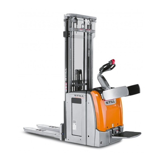
Still EXV 16 Original Instructions Manual
Pallet stacker
Hide thumbs
Also See for EXV 16:
- Original instructions manual (192 pages) ,
- Original instructions manual (180 pages)

Related Manuals for Still EXV 16


Summary of Contents for Still EXV 16
- Page 1 Original instructions Pallet stacker EXV 14 / 16 / 20 EXV 14i / 16i / 20i EXV-SF 14 / 16 / 20 EXV-SF 14i / 16i / 20i EXP 14 / 16 / 20 0301 0303 0305 0323 0324 0325 0326 0327 0328 0329 0330 0331 0332 0333 0334 45758043402 EN - 02/2015...
-
Page 3: Table Of Contents
Table of contents Introduction Forklift data ............2 General information . - Page 4 Table of contents Safety devices ............20 Location of safety devices .
- Page 5 Table of contents Safety instructions relating to use of the truck ....... 62 Truck transport and lifting .
- Page 6 Table of contents Maintenance General Information ..........98 Preliminary maintenance operations .
-
Page 7: Introduction
Introduction... -
Page 8: Forklift Data
Introduction Forklift data Forklift data We recommend that you record the principal forklift data in the following table so that they are available if required by the sales network or authorised service centre. Type Serial number Date of delivery General information •... - Page 9 Introduction How to Consult the Manual CAUTION NOTE Failure to observe the instructions highlighted with This symbol is used to provide additional this symbol may cause damage to the forklift and, information. in some cases, result in warranty invalidity. ENVIRONMENT NOTE Failure to observe the instructions highlighted with this symbol may cause environmental damage.
-
Page 10: Date Of Edition And Latest Update Of This Manual
Introduction Date of edition and latest update of this manual Date of edition and latest update of this manual The publication date of these operating instructions is printed on the cover sheet. The manufacturer makes continuous efforts to improve its industrial trucks, and therefore reserves the right to implement changes and to accept no claims concerning the information provided in this manual. -
Page 11: Ec Declaration Of Conformity In Accordance With Machinery Directive
Introduction EC declaration of conformity in accordance with Machinery Directive EC declaration of conformity in accordance with Machinery Di- rective Declaration STILL GmbH Berzeliusstraße 10 D-22113 Hamburg Germany We declare that the according to these operating instructions Industrial truck according to these operating instructions Model conforms to the latest version of the Machinery Directive 2006/42/EC. -
Page 12: Technical Service And Spare Parts
Introduction Technical service and spare parts Technical service and spare parts For scheduled maintenance and any repairs to the technical characteristics of the forklift over the forklift, contact only the authorised service time. network. Only original spare parts provided by the man- The authorised service network has personnel ufacturer may be used for forklift maintenance trained by the manufacturer, original spare... -
Page 13: Working Conditions
Introduction Working conditions • transporting and/or lifting people; • turning and/or moving sideways on slopes (upwards or downwards); • pushing or pulling loads; • colliding with stationary and/or mobile • moving upwards or downwards on a slope structures; with the load facing downwards; •... -
Page 14: Applied Equipment
Introduction Applied equipment Applied equipment To use equipment that has not been applied, • add a label with the new residual capacity is please contact the authorised sales network, • provide documentation on the equipment in order to: (user and maintenance manual and EC •... -
Page 15: Packaging
Introduction Environmental considerations Packaging During delivery of the truck, certain parts are packaged to provide protection during transport. This packaging must be removed completely prior to initial start-up. ENVIRONMENT NOTE The packaging material must be disposed of properly after delivery of the truck. 45758043402 [EN]... - Page 16 Introduction Environmental considerations 45758043402 [EN]...
-
Page 17: Safety
Safety... -
Page 18: Safety Guidelines
Safety Safety guidelines Safety guidelines General Precautions regulations integrate those in the manual NOTE "Rules for approved use of industrial vehicles". Some safety regulations to be followed when using the forklift are listed below. These General Safety Rules • Only allow qualified, trained and authorized •... -
Page 19: Battery Connection Cables
Safety Safety guidelines the wheels, which affect the entire structure of the forklift. CAUTION DO NOT pass over cracks or damaged parts of the floor with the forklift. Dirt and any objects in the work path must be removed immediately. Battery connection cables CAUTION Using sockets with NON-ORIGINAL battery con-... -
Page 20: Safety Regulations Relative To Operating Materials
Safety Safety guidelines Safety Regulations Relative to Operating Materials Rules for handling and disposing of Oils operating materials • Do not allow to come into contact with the skin. ENVIRONMENT NOTE • Do not inhale oil vapors. Improper use and disposal of operating and •... -
Page 21: Residual Risks
Safety Residual risks and disposal of the life-expired battery must NOTE be carried out as required by law. We advise you to contact the authorised service network For greater information, consult the specific that is equipped for eco-friendly disposal in battery manual that comes with the battery. - Page 22 Safety Residual risks • Fire and explosion risks due to batteries and electrical voltages. • Human error resulting from failure to observe the safety guidelines. • Unrepaired damage or defective and worn components. • Insufficient maintenance and testing • Use of incorrect consumables •...
-
Page 23: Electromagnetic Radiation
Safety Electromagnetic radiation Electromagnetic radiation The limit values for electromagnetic emissions and for immunity relative to the forklift are those provided by the EN 12895 standard. Non-ionised radiation If the forklift is equipped at the factory or later with devices that emit non-ionising radiation (such as radio transmitters, RFID players, data terminals, scanners, etc), the compatibility of such devices must be verified... -
Page 24: Vibrations
Safety Vibrations Vibrations Value of the vibrations to which the hands- CAUTION arms are exposed: The value expressed above can be used to com- pare forklift trucks of the same category. It cannot ā < 2.5 m/s be used to determine the operator’s daily expo- The value complies with Harmonised Euro- sure to vibrations during real operation of the truck;... -
Page 25: Safety Tests
Safety tests Regular safety inspection of the truck Safety inspection based on time and extraordinary incidents STILL GmbH Hamburg The operating company must ensure that the truck is checked at least once a year, or Regelmäßige Prüfung following noteworthy incidents. -
Page 26: Safety Devices
Safety Safety devices Safety devices Location of safety devices Main safety devices on the truck 10-11-12 OM2308 Emergency shutdown handle. Operator anti-crush safety button. Protects Tiller position sensor. The truck will not the operator from potential crushing by move if the tiller is not in the correct usage braking the truck. - Page 27 Safety Safety devices Operator side protection. Prevents the Automatic truck braking when the tiller is operator from falling from the platform during released by the operator ride-on driving (if present). Horn. Used to indicate the presence of the Protective covers fastened with screws. truck during travel.
-
Page 28: Damage, Defects And Misuse Of Safety Devices
Safety Safety devices Damage, defects and misuse of safety devices The driver must report any damage or other defects to the truck or attachment immediately to the supervisory personnel. Trucks and attachments that are not functional or safe may not be used until they have been properly repaired. -
Page 29: Overview
Overview... -
Page 30: Technical Description
• Telescopic "post": two-section telescopic The trucks described in this manual EXV 14, post without free lifting and two side cylin- EXV 16, EXV 20, EXV 14i, EXV 16i and EXV ders 20i, EXV 14-SF, EXV 16-SF, EXV 20-SF, EXV •... - Page 31 Overview Technical description On-board equipment Braking: • when the accelerator is released, The on-board equipment includes: • Select the direction of travel • a glove compartment for storing adhesive • controlled by the anti-crush safety button tape, gloves,pens etc., • electromagnetic safety device, controlled •...
-
Page 32: Overview
Overview Overview Overview OM2284 On / off key Straddles Lifting post Load rollers Helm head Battery plug/socket Emergency stop handle Forks Helm Battery compartment hood With operator side protective guards Anti-shearing guard Bonnet Diagnostic test socket Service technical Pivoting wheel assistance Operator’s Platform Digicode- Numeric Keypad... -
Page 33: Instruments And Controls
Overview Instruments and controls Instruments and controls Start/stop key The key has two positions: 0 = Stop. No voltage to the circuit (Key removal position) I = Start. Circuit powered 45758043402 [EN]... -
Page 34: Display
Overview Instruments and controls Display NOTE The messages shown in the following illustra- tions are indicative and may vary depending on the language chosen by the operator via the display. Buttons and indicator lights – By pressing the button (A), you can select the required performance for the truck. - Page 35 Overview Instruments and controls • (7) The indicator light comes on for sched- uling truck routine maintenance • (8) The indicator light comes on when there is a problem inside the truck (CAN etc.) – By pressing the button (B), you move backwards between the entries for each screen or backwards between one screen and the other.
- Page 36 Overview Instruments and controls Setting – The following can be set on the Setting screen: • Language Language • Unit of measurement Units • Date Dateformat • Time • Brightness Date • Contrast Time • Date format SETTING Error OM2307 –...
- Page 37 Overview Instruments and controls – The message warns that the maximum height set for the forks has been reached (optional function called" lifting block h3=..."). The word "OK" appears on the display in the red rectangle (E). Avvertimento – To delete the message and be able to lift Altezza superata the forks and the load higher, keep the first button on the right on the keypad (D)
- Page 38 Overview Instruments and controls – The message may appear on the display when lifting approximately 1500 mm from the ground (only for trucks for the version with platform and side protection). To remove the message from the display, lower the load or close the operator side protection (for more information, also see ⇒...
- Page 39 Overview Instruments and controls – When the battery is charging, the display shows that battery charging is in progress. Carica in corso 11.8 hrs OM2302 – The message highlights a problem inside the truck. Switch the truck off and on again. If the message does not disappear, contact the technical service department authorised by the manufacturer.
-
Page 40: Emergency Shutdown Handle
Overview Instruments and controls – The message highlights that the motor has overheated. Shut down the truck and wait for it to cool down. If the message reap- pears, contact the technical service depart- ment authorised by the manufacturer. CAUTION Temperatura motore If the Error screen displays messages other than troppo alta (anormala) -
Page 41: Tiller Controls
Overview Instruments and controls Tiller controls 1 — Tiller head handle 2 and 3 — Traction control throttle 4 — Fork lowering button 5 — Fork lifting button 6 — Horn button 7 — Anti-crush button 8 — Slow speed button (optional — Creep Speed) 9 —... - Page 42 Overview Instruments and controls tically triggered just before the end of the stroke (soft landing) Fork lifting button (5) • Press the button (5) to lift the forks and reach the maximum height. • Fork movement can be stopped at any time by releasing the button (5).
- Page 43 Overview Instruments and controls Slow-speed button (8) (optional — Creep Speed) • The button (8) is fitted with the optional "tiller always active" option (Creep Speed). • Keeping the button (8) pressed while turning the throttle (2 – 3) activates the slow speed, regardless of the tiller position.
-
Page 44: Tiller
Overview Tiller Tiller Tiller positions Position the tiller in accordance with the truck functions With the truck stopped, the two following tiller positions are available: • Position (1) = working position. In this position, the operator can begin travel using the throttle. In this position, the operator can begin lifting or lowering the forks using the appropriate throttle. - Page 45 Overview Tiller “Timone sempre attivo” version (optional — Creep Speed) • Position (2) using the "tiller always active" function (optional) = slow speed position This function is activated by pressing the slow speed button on the tiller (3) and rotating the traction control throttle (4) or by pressing the slow speed button and the fork lifting button.
-
Page 46: Combi Tiller (If Present)
Overview Tiller Combi tiller (if present) Instructions for opening the combi tiller CAUTION Perform the operation, preferably before starting the truck and only when the truck is stationary. Carrying out the operation when the truck is moving is prohibited. NOTE The preferred means of use with the combi tiller open is in pedestrian mode (operated "from the ground"). - Page 47 Overview Tiller – The tiller is open. Instructions for closing the combi tiller CAUTION Perform the operation, preferably before starting the truck and only when the truck is stationary. Carrying out the operation when the truck is moving is prohibited. NOTE The preferred means of use with the combi tiller closed is in ride on mode (operated from...
-
Page 48: Optispeed Tiller (Only Present On Exv And Exvi Versions)
Overview Tiller OptiSpeed tiller (only present on EXV and EXVi versions) The different work zones of the tiller depending on the tilt are explained below: • In zone (1), the brake is applied and the truck cannot be moved. • In zone (2), the maximum authorised speed varies according to the tilt of the tiller. -
Page 49: Types Of Lifting Masts
Overview Types of lifting masts Types of lifting masts Your truck may be fitted with one of the following masts: • Simplex • Telescopic • NiHo • Triplex Simplex When the "lift" button is pressed, the fork carriage is raised to the height h3 by the central cylinder via a chain. - Page 50 Overview Types of lifting masts Triplex The function is identical to that of the NiHo mast, but has a greater lift height with the same mast height. CAUTION In locations with a low ceiling, be aware that the load height may be greater than the mast height. 0252_003-100-V2 45758043402 [EN]...
-
Page 51: Side Protection
Overview Side protection Side protection Description The side protection has been designed to protect the operator when the truck is used in ride on mode. There are two positions: – Position "A" = side protection closed. Position used when the operator is using the truck in pedestrian mode (operated from the "ground") with the platform closed. - Page 52 Overview Side protection CAUTION Always lower the side protection bars before re-clo- sing them. Otherwise the side protective guards will not close and this may damage the hoods. DANGER Do not sit on the side protection bars. DANGER Do not climb on the side protection bars. 45758043402 [EN]...
-
Page 53: Platform
Overview Platform Platform Description The platform can take up three positions A, B, Position "A" = platform closed. This position is used when the truck is in pedestrian mode (operated from the "ground") with the side protection closed. Position "B" = platform in the intermediate position: in this position, the truck traction is locked. - Page 54 Overview Platform If the platform is closed "A" and the side protection is open, the traction is locked. Moving the platform To lift or lower the platform, move the platform floor by hand. CAUTION Danger of crushing hands. When closing the platform, do not leave your hands between the platform and the hood.
-
Page 55: Definition Of Directions
Overview Definition of directions Definition of directions Definition of directions for EXV, EXVi, EXP Directions also valid for EXV-SF and EXVi-SF versions with platform closed and pedestrian mode operation Direction of movement defined by the regula- tions: • Reverse travel (1) •... -
Page 56: Markings
Overview Markings Markings Location of labels A > < Pb+Sb OM2291 "Truck capacity diagram" label "On-board battery charger" label "Operator side protection" usage label (for Annual checks label (Germany only) the version with operator platform only) "Operator platform capacity diagram" label "Hook"... - Page 57 Overview Markings Description of labels (9) This label is only present on the version with the on-board battery charger. The label (1) This label indicates the permissible load on highlights the possibility of choosing the the forks depending on load centre of gravity charging curve.
-
Page 58: Serial Number
Overview Markings Serial number xx xxxx x xxxxx NOTE Please quote the serial number with all technical questions. The serial number contains the following information: 1 Production location 2 Type 3 Year of production 4 Sequential number 7090_921-004 Data plate NOTE Please indicate the serial no. -
Page 59: Capacity Plate
Overview Markings Capacity plate – The identification plate indicates the follow- ing data: • (1) CDG = distance "C" from the centre of gravity of the load on the forks to the fork carriage (in mm) • (2) h = lift height of the forks from the ground (in mm) •... -
Page 60: Chassis Frame Labelling
Overview Markings Chassis frame labelling OM2312 The truck’s serial number is marked (A) on the chassis frame. 45758043402 [EN]... -
Page 61: Options And Variants
Overview Options and variants Options and variants List of options and variants List: • Various types of tyre for the drive wheel • Various types of load rollers • Tiller always active (Creep Speed) • Various types of battery • Various lift masts and lift heights •... -
Page 62: Straddle Automatic Lowering (Optional)
Overview Options and variants NOTE The above list is only a summary. Some optionals are NOT available on all models. For more information, please refer to the price list and contact the authorised sales network. Straddle automatic lowering (op- tional) This option is available for all trucks equipped with straddle initial lift. -
Page 63: Accessories Mounting Bar With Data Socket
Overview Options and variants Accessories mounting bar with data socket The optional data socket (6 and 7) is fitted on the relevant accessories mounting bar (3). The pre-wired data socket (6) connected to the truck has the following features: • Voltage 24 V •... -
Page 64: Digicode Option
Overview Options and variants Digicode option SWITCH ON (operating mode) SWITCH OFF and awaiting code Programming mode active Faulty key or incorrect code Delay of automatic switch-off OPERATING MODE Operation Warning red off continuous * 1 2 3 4 5 # green (1)(PIN correct) default 1 2 3 4 5... - Page 65 Overview Options and variants PROGRAMMING MODE — to be carried out with the truck switched off (2) To reactivate the default Restoring administrator code the initial (00000000), please administrator contact your agent or code nearest dealer. The power supply switches off red flashing green Activating the automatically after...
-
Page 66: Battery Electrolyte Level Indicator Led (Optional)
Overview Options and variants Battery electrolyte level indicator LED (optional) There are two versions of the LED: • 1) Located on the battery • 2) Located next to the battery plug. The LED indicates whether it is necessary to top up the distilled water in the battery. Operation: •... -
Page 68: Authorised And Safe Use
Authorised and safe use Authorised and safe use Intended use of the trucks CAUTION This machine is intended for the transport of loads packed on pallets or in industrial containers de- signed for this purpose, as well as for placing pallets into and removing pallets from stock. - Page 69 Authorised and safe use • The truck has not been designed to trans- port anyone other than the operator and must not be used for this purpose. • The operator must always stay within the truck clearance. • Stay in the safety area (working area defined by the manufacturer).
-
Page 70: Truck Transport And Lifting
Truck transport and lifting the surrounding fixed installations. The height depends on the lift height and the dimensions of the load. Refer to the technical characteristics. Regulations regarding the traffic routes and the manoeuvring areas Only traffic routes authorised by the operator or his agent may be used. -
Page 71: Transport
Truck transport and lifting Transport – Disconnect the battery connector. Chocking the truck – Secure the truck against rolling and sliding with chocks (1). Lashing down the truck – Attach the lashing ropes (2) to the mast. 0252_003-010 Climatic Conditions for Transport and Storage The forklift must be protected from atmo- spheric agents during transport and storage. -
Page 72: Loading And Unloading The Truck
Breaking-In Loading and unloading the truck To load and unload the truck, use a loading bridge or a lift (with a slope and structural strength compatible with the performance and weight of the truck as stated by the manufacturer, and that is suitably positioned and anchored). -
Page 73: Checks And Actions Prior To Commissioning
Checks and actions prior to commissioning Checks and actions prior to commissioning List of checks before use WARNING • The wheels must not show any sign of damage or heavy wear. They must be Damage or other faults on the truck or attachments correctly mounted. - Page 74 Checks and actions prior to commissioning is released. The throttle must not remain - Test that the truck goes into forwards/re- activated or locked. verse travel using the control throttle. • Test that the truck brakes and stops when - Climb down from the step plate and the throttle is released while driving.
-
Page 75: Operator Position
Operator position Operator position Operator’s position for version without platform The driving position is in pedestrian version (driving on "the ground"). The operator should drive the truck using the driving and lifting controls located on the helm head. DANGER All other positions should be considered incorrect and dangerous. -
Page 76: Operator Position For Version With Platform
Operator position Operator position for version with platform There are two driving positions: • Pedestrian mode driving position — "oper- ated from the ground" • Ride on mode driving position Pedestrian mode driving position — "operated from the ground" The operator should drive the truck using the driving and lifting controls located on the tiller head. - Page 77 Operator position Ride on mode driving position The operator should drive the truck using the driving and lifting controls located on the tiller head. In this configuration: • The platform must be fully open • With the side protection closed, the max- imum speed of travel is limited for safety reasons.
-
Page 78: Use Of The Truck
Use of the truck Use of the truck Stopping the truck in emergencies In an emergency, the power supply to all functions on the truck can be shut down. – Press the emergency shutdown handle. This blocks all of the truck functions, so the truck will brake and stop. -
Page 79: Truck Operation
Use of the truck Truck operation Pedestrian drive mode version (operated • Manually open the operator protective from the "ground") guards • Mount the platform • Grip the tiller head correctly • Tilt the tiller to the working position • Tilt the tiller to the working position •... -
Page 80: Truck Steering Direction
Use of the truck Truck steering direction OM2313 Use the tiller to steer during travel. • When the tiller is turned clockwise (H) while travelling towards (A), the truck steers • When the tiller is turned anti-clockwise (G) towards (E) while travelling towards (A), the truck steers •... -
Page 81: Using The Truck With The "Tiller Always Active - Creep Speed" Function (Optional)
Use of the truck Using the truck with the "Tiller always active — Creep Speed" function (optional) The "tiller always active" function can be enabled when operating the truck in confined spaces. This function allows the truck to be operated with the tiller in any position. -
Page 82: Reverse Drive
Use of the truck Reverse drive Reverse of direction without load on forks Reverse of direction with load on forks • To reverse direction when travelling without • To reverse direction with a load on the fork a load on the fork arms, turn the traction arms, release the traction control throttle control throttle in the opposite direction of and wait for the truck to come to a stop. -
Page 83: Parking And Stopping The Truck
Use of the truck Parking and stopping the truck • Parking in pre-arranged and designated areas. • Lower the forks to the ground. • Release the tiller to activate the parking brake. • For the version with platform, close the platform and the operator’s protective devices. -
Page 84: Forklift Use In Cold-Storage Rooms
Use of the truck Forklift Use in Cold-Storage Rooms. A truck specifically equipped for cold-storage CAUTION rooms must be used when working at temper- If the truck has been working in environments at atures below +5°C. temperatures below -5°C and it is taken outside the cold-storage room, let it stand either for a sufficien- Forklifts equipped for working in cold climates tly long time to allow evaporation of any condensa-... -
Page 85: Movement Of The Load
Movement of the load Movement of the load Safety guidelines for handling loads WARNING Closely observe the following instructions before picking up loads. Never touch or stand on moving parts of the truck (e.g. lifting devices, equipment or devices for picking up loads). WARNING Risk of crushing hands and feet when using the lift. - Page 86 Movement of the load CAUTION Driving or turning with the forks raised above appro- ximately 300 mm from the ground is prohibited. It is only allowed at reduced speed when depositing a load and/or picking up a load from shelving. CAUTION Insert forks in pallets from the correct side, as shown in the illustration (only permitted for EXP...
- Page 87 Movement of the load NOTE Further information on the general rules of truck use and taking up and depositing loads is provided in the "Safety Regulations for Industrial Forklift Use" manual attached to this manual. 45758043402 [EN]...
-
Page 88: Checks To Be Carried Out Before Lifting A Load
Movement of the load Checks to be carried out before lifting a load WARNING Never exceed the capacity of the truck. This ca- pacity is based on the centre of gravity and the lift height of the load. Comply strictly with the load diagram! It is not permitted to increase the capacity by adding extra weight to the truck. -
Page 89: Adjusting The Fork Distance (If Present)
Movement of the load Adjusting the fork distance (if present) – Raise the locking lever (1), or raise and rotate the knob (2) by 180° depending on the type of lock, (1) or (2), installed on the forks. – Move the fork arms (3) in relation to the dimensions of the load to be lifted. -
Page 90: Automatic Speed Reduction With Forks Raised Above The Safety Sensors
Movement of the load Automatic speed reduction with forks raised above the safety sensors As indicated in the safety devices chapter, (see ⇒ Chapter "Location of safety devi- ces", P. 2-20), the truck is equipped with: • 500-mm sensor Automatic speed reduction with forks raised approximately 500 mm above the ground. - Page 91 Movement of the load DANGER Pay attention to the part of the forks protruding from the load to be lifted. Do not strike the wall, the shelving or other loads and/or objects behind the load to be picked up. – Lift the load a few centimetres from the ground and read the "Transporting loads"...
- Page 92 Movement of the load – Insert the forks as far as possible below the load. If possible, the forks should be inserted far enough in that the load is resting against the fork carriage. The load centre of gravity must be centred between the forks. DANGER Pay attention to the part of the forks protruding from the load to be lifted.
- Page 93 Movement of the load – Lower the load to the transport position, approximately 300 mm from the ground, and read the "Transporting loads" section. 45758043402 [EN]...
-
Page 94: Transporting Loads
Movement of the load Transporting loads As a general rule, loads must be transported one by one (e.g. pallets). Transporting several loads at once is only authorised: • If the safety requirements are met • On the orders of the supervisor in charge The operator must ensure that the load is properly packaged. -
Page 95: Deposit The Load
Movement of the load Deposit the load. • Approach the load deposit area. • Lower the fork arms until the load is de- posited in the desired area and release the fork arms from the load. • Back up with the forklift. DANGER Never leave the forklift with the forks raised whether loaded or not. -
Page 96: Using The Truck On Inclines, Loading Bridges And Lifts
Movement of the load Using the truck on inclines, loading bridges and lifts. Driving on inclines Using the truck on a lift When driving the truck up or down inclines, Using the truck on lifts is only allowed if the you must not exceed the values for inclines lift has sufficient load capacity (check the indicated in the chapter "Technical data". -
Page 97: Charging The Battery
Charging the battery Charging the battery Internal accessibility Opening the battery cover – To access the battery and respective plug/outlet, raise the battery compartment cover using the appropriate handle. – If you need to recharge the battery, discon- nect the battery plug and socket by means of the appropriate handle. - Page 98 Charging the battery DANGER Before accessing the inner parts of the truck, carefully follow the instructions given in Chapter 5, entitled "Maintenance". Access to the inner parts of the truck by personnel not authorised by the manufacturer is forbidden. 45758043402 [EN]...
-
Page 99: Battery Recharging
Charging the battery Battery Recharging CAUTION • Turn on the external battery charger. • Connect plug the battery charger in to begin The battery is recharged with the forklift off. charging. • After the battery charging operation is DANGER completed, turn off the battery charger. •... -
Page 100: Recharging The Battery Using The On-Board Battery Charger (Optional)
Charging the battery • gel battery with a capacity below 210 Ah, • gel battery with a capacity greater than 210 CAUTION The charger is supplied in the NEUTRAL position. Recharging the battery using the on-board battery charger (optional) CAUTION Charge the battery with the engine switched off and the start key removed. -
Page 101: Battery Type
Charging the battery Battery type Trucks can be fitted with different types of battery. Observe the instructions on your battery type plate, as well as the specifications defined in the chapter "Technical data". WARNING The weight and size of the battery influence the stability of the truck. - Page 102 Charging the battery and the battery outlet is inserted. If the truck is enabled for side removal of the battery, the truck can only be operated once the battery is fixed in place properly using the battery locking system. 45758043402 [EN]...
-
Page 103: Maintenance
Maintenance... -
Page 104: General Information
Maintenance General Information General Information To keep your forklift in good condition, carry DANGER out the servicing indicated regularly, within the Scheduled maintenance and repairs must be times indicated and using the consumption done by the service network authorised by the materials provided for that purpose, as speci- manufacturer in order to maintain the machine fied on the following pages. -
Page 105: Scheduled Maintenance
Maintenance Scheduled maintenance Scheduled maintenance Summary Table of Maintenance Operations Com- Operations Intervals in hours pleted 1000 2000 5000 Checks and inspections prior to commis- sioning Check the hydraulic oil level Check insulation between chassis and electric motors Check insulation between chassis and electronic control Check condition and correct fixing of battery and truck wiring... - Page 106 Maintenance Scheduled maintenance Com- Operations Intervals in hours pleted 1000 2000 5000 Check operator side protection (if present) Check for wear on the forks (EXP only) Check the tightness of the retaining bolts of the straddles (EXP only) Check hydraulic oil Service the lift mast and check lateral clearance of pins Replace the pump unit filters...
-
Page 107: Maintenance As Required
Maintenance Maintenance as required Maintenance as required Cleaning the Forklift Cleaning depends on the type of use and the Use water-dampened rags to clean the parts workplace. Should the truck come into contact of the body. with highly aggressive elements such as salt CAUTION water, fertilizers, chemical products, cement, etc., it should be cleaned as carefully as... -
Page 108: Fuses
Maintenance Maintenance as required Fuses • Turn off the truck and perform the prelimi- nary maintenance operations CAUTION Before carrying out any operations on the electrical system, turn the truck power supply off by discon- necting the battery connector. CAUTION Before changing the fuse, eliminate the cause that led to its blowing. - Page 109 Maintenance Maintenance as required • Lift the battery using a hoist suitably sized for the weight of the battery. • Change the battery and refit it by following the above steps in reverse order. CAUTION To decide which type of battery to use, check the battery characteristics provided in the "TECHNI- CAL DATA"...
- Page 110 Maintenance Maintenance as required – When inserting and/or extracting the battery from the top (2), the battery must be tilted as shown. CAUTION Before using the truck, refit the protective guard (1). Using the truck without the anti-shearing protective guards is prohibited. OM2311 45758043402 [EN]...
-
Page 111: Battery Replacement With Side Removal
– Place the manufacturer-approved battery side-removal roller unit next to the truck; position it so that it is still and stable; adjust the height of the roller unit so that it is level with the underside of the battery at the battery compartment. - Page 112 Maintenance Maintenance as required on the previously prepared external roller unit. – Hook the battery at the two points (8) with a sling or chain. – Lift the battery and remove it. DANGER Use a crane with a suitable lifting capacity for the weight of the battery.
- Page 113 Maintenance Maintenance as required CAUTION When closing the battery cover, take care to po- sition the cables of the battery male connector correctly so as not to damage them. NOTE After having positioned the battery holddown, check that there is little or no clearance in the battery compartment.
-
Page 114: Putting Out Of Commission
Maintenance Putting out of commission Putting out of commission General Information The operations to be performed for "Tem- porary decommissioning" and "Permanent decommissioning" are listed in this chapter. 45758043402 [EN]... -
Page 115: Forklift Towing
Maintenance Putting out of commission Forklift Towing The forklift may not be towed in the case of breakdown. The forklift must be lifted with due caution, as described on the preceding pages. Temporary Putting Out of Commission The following operations must be performed •... - Page 116 Maintenance Putting out of commission 45758043402 [EN]...
-
Page 117: Technical Data
Technical data... -
Page 118: Exv And Exvi Overall Dimensions
Technical data EXV and EXVi overall dimensions EXV and EXVi overall dimensions 45758043402 [EN]... -
Page 119: Exv-Sf And Exvi-Sf Overall Dimensions
Technical data EXV-SF and EXVi-SF overall dimensions EXV-SF and EXVi-SF overall dimensions 45758043402 [EN]... -
Page 120: Datasheet
Technical data Datasheet Datasheet Datasheet (VDI) EXV 14 / EXV 16 and EXV 14i / EXV 16i CHARACTERISTICS EXV 14 / EXV 16 EXV 14i / EXV 16i Power unit: electric, diesel, Electric Electric petrol, LPG Drive type: manual, pedestrian,... - Page 121 Technical data Datasheet Track width, drive side (mm) Track width, load side (mm) DIMENSIONS EXV 14 / EXV 16 EXV 14i / EXV 16i 4.2 Height of mast, lowered h1 (mm) 1915 1915 h2 (mm) 4.3 Free lift h3 (mm)
- Page 122 (19) 10 (8) 10.0/23.0 with/without load 5.10 Service brake Electric Electric EXV 14 / EXV 16 EXV 14i / EXV 16i TRANSMISSION 6.1 Traction motor, S2=60 min 6.2 Lifting motor, S3=15% Battery acc. to DIN 43 2 PzS 2 PzS 531/35/36 A, B, C, no 6.4 Voltage/Nominal capacity...
- Page 123 Technical data Datasheet (11) Values with fender (12) Value with straddles lowered +17 mm (13) Value with straddles lowered +42 mm (14) Value with straddles lowered +78 mm (15) ±5% (16) Speed in pedestrian mode - Speed standing without side protection - Speed standing with side protection (16) On slopes with gentle start and forks raised (geometric limit with start of slope at =...
- Page 124 Technical data Datasheet Axle load with load, drive 1040/1619/1059/1800 971/1658/979/1850 side/load side Axle load without load, 955 / 304 962 / 268 drive side/load side WHEELS EXV-SF 14 / EXV-SF 16 EXV-SF 14i / EXV-SF 16i Tyres Polyurethane Polyurethane Drive wheel sizes Ø...
- Page 125 Technical data Datasheet Ground clearance, centre / 150 4.32 (mm) of wheelbase (3) (4) (11) 2390 /2777 Aisle width with pallets 800 (4) (7) Ast (mm) 2406 /2795 4.34 (4) (7) (11) x 1200 (3) (4) (13) 2404 /2791 Aisle width with pallets (4) (7) Ast (mm) 2444 /2833...
- Page 126 Technical data Datasheet (4) Value with battery such as 6.3 (+75 mm with 3 PzS and +150 mm with 4PzS) (5) Truck with tandem rollers (6) Value with Tele mast h = 2844 mm. For other values see mast table (7) With load rack, mandatory for -SF (8) Value with platform lowered (9) The fork thickness value indicated is for use...
- Page 127 Technical data Datasheet 1.5 Load capacity 2000 (2000) 2000 (kg) 1.6 Load centre (mm) Load distance, (2) (3) /646 centre of drive (mm) axle to fork 1425 / 1347 1.9 Wheelbase 1425 (mm) WEIGHT EXV 20 EXV 20i Service weight (with 1505 1439 battery)
- Page 128 Technical data Datasheet 4.19 Overall length without load 2065 2065 (mm) Length including fork 4.20 (mm) shoulder 4.21Total width (mm) s/e/l (mm) 4.22Fork dimensions 73/210/1150 73/210/1150 4.24 Fork carriage width (mm) 4.25 Fork spread 580 / 680 580 / 680 (mm) 4.26 230 / 330...
- Page 129 Technical data Datasheet OTHER EXV 20 EXV 20i 8.1 Type of drive control AC control AC control Noise level at operator’s ≤ 66 ≤ 66 (1) In brackets: capacity on the forks for the version with fork initial lift (i) (2) Values for Tele or NiHo mast (x value -26 mm, l +26 mm with Triplex mast)
- Page 130 Technical data Datasheet Drive type: manual, pedestrian, Pedestrian/Standing Pedestrian/Standing stand-on, seated, order picker 1.5 Load capacity 2000 (2000) 2000 (kg) 1.6 Load centre (mm) Load distance, (2) (3) /646 centre of drive (mm) axle to fork 1425 / 1347 1.9 Wheelbase 1425 (mm) WEIGHT...
- Page 131 Technical data Datasheet Height of tiller arm in h14 (mm) 1175 / 1380 1175 / 1380 driving position, min/max 4.15 Fork height, lowered (mm) (2) (6) (2) (6) 4.19 Overall length without load 2108 /2516 2108 /2516 (mm) Length including fork (2) (6) (2) (6) /1366...
- Page 132 Technical data Datasheet 6.5 Battery weight (±5%) Energy consumption acc. kWh/h 1.48 1.62 to VDI cycle OTHER EXV-SF 20 EXV-SF 20i 8.1 Type of drive control AC control AC control Noise level at operator’s ≤ 66 ≤ 66 (1) In brackets: capacity on the forks for the version with fork initial lift (i) (2) Values for Tele or NiHo mast (x value -26 mm, l...
-
Page 133: Exp Overall Dimensions
Technical data EXP overall dimensions EXP overall dimensions 45758043402 [EN]... -
Page 134: Datasheet
Technical data Datasheet Datasheet Datasheet (VDI) EXP 14 / EXP 16 / EXP 20 CHARACTERISTICS EXP 14 EXP 16 EXP 20 Power unit: electric, Electric diesel, petrol, LPG Drive type: manual, pedestrian, stand-on, Pedestrian seated, order picker 1.5 Load capacity 1400 1600 2000... - Page 135 Technical data Datasheet Track width, drive side (mm) Track width, load side 1000/1200/1400 (mm) DIMENSIONS EXP 14 EXP 16 EXP 20 1912 4.2 Height of mast, lowered h1 (mm) 1912 h2 (mm) 1276 1286 1286 4.3 Free lift h3 (mm) 4266 4026 4.4 Lift...
- Page 136 Technical data Datasheet PERFORMANCE EXP 14 EXP 16 EXP 20 Travel speed km/h 6.0 / 6.0 with/without load Lifting speed, 0.16/0.30 0.15/0.30 0.15/0.30 with/without load Lowering speed, 0.40/0.35 0.40/0.35 0.31/0.31 with/without load Climbing ability KB 5’, (9) (10) 8 / 23 with/without load Electromagnetic 5.10 Service brake...
-
Page 137: Batteries
Technical data Batteries Batteries Battery Bat- Volt- TROG extrac- tery Element height TROG Battery type (mm) di- TROG tion capac- (mm) colour mension type ity (Ah) 2 PzV (gel) 624 x 2 PzV (gel) 212 x 24 V 7021 2 PzS (lead) 570–575 Vertical 2 PzS (lead) - Page 138 Technical data Batteries 3 PzV (gel) 3 PzS (lead) 3 PzS (lead) 3 PzV (gel) 3 PzV (gel) 3 PzS (lead) Side ex- 3 PzS (lead) traction 4 PzV (gel) 4 PzV (gel) 4 PzS (lead) 45758043402 [EN]...
-
Page 139: Supply Table
Technical data Supply table Supply table Supply table for standard trucks Quantity Element to be supplied Lubricants Hydraulic system HLF 32 Reduction gear unit ARAL DEGOL GS 220 General and mast lu- TUTELA MP02 brication Chain lubrication STRUCTOVIS EHD Supply table for cold-storage trucks Quantity Element to be supplied Lubricants... - Page 140 Technical data Supply table 45758043402 [EN]...
- Page 141 Index Location of labels ....50 Battery Disposal ..... . . 8 Operator position .
- Page 142 Index Types of lifting masts ....43 Triplex ..... . . 44 Update of this manual .
- Page 144 STILL GmbH Berzeliusstrasse 10 D-22113 Hamburg Ident no. 45758043402 EN...
Need help?
Do you have a question about the EXV 16 and is the answer not in the manual?
Questions and answers