
Related Manuals for Still EXG-10


Summary of Contents for Still EXG-10
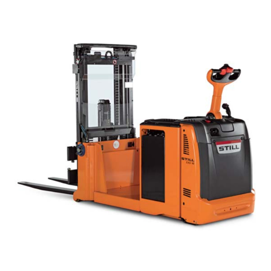
- Page 1 Original instructions Counterweight pallet stacker EXG-10 EXG-12 EXG-16 1217 1218 1219 1170 801 15 09 EN - 07/2012...
-
Page 3: Table Of Contents
Table of contents Introduction Electric pallet stacker ..........2 Your industrial truck . - Page 4 Table of contents Safety regulations for handling consumables ....... 21 Permissible consumables .
- Page 5 Table of contents Driving on loading bridges ..........60 Transporting pallets or other containers .
- Page 6 Table of contents Checking the battery charging status ........96 Opening the battery cover .
-
Page 7: Introduction
Introduction... -
Page 8: Electric Pallet Stacker
Introduction Electric pallet stacker Electric pallet stacker Electric counterweight pallet stacker types – Side access EXG 10, EXG 12 and EXG 16 are designed for The power supply to the traction motor is stacking. controlled by an electronic control module They can also be used to transport pallets of a which provides complete control of the speed, maximum weight 1000 kg (EXG 10), 1200 kg... -
Page 9: Your Industrial Truck
Introduction Your industrial truck Driver’s compartment Options Various options are available on EXG trucks: Pedestrian model: • the speed is limited to 6 km/h • Cold Store option • the tiller has all the control units and pro- • gradual carriage stop vides the steering for the truck. -
Page 10: Ec Declaration Of Conformity
Introduction Your industrial truck EC declaration of conformity Declaration STILL GmbH Berzeliusstrasse 10 22113 Hamburg GERMANY We declare that the machine according to these operating instructions Industrial truck according to these operating instructions Model conforms to the latest version of the Machinery Directive 2006/42/EC. -
Page 11: Information About Documentation
Introduction Information about documentation Information about documentation Documentation scope • Operating instructions document Please quote these numbers for all technical enquiries. • Operating instructions for attachment parts (special equipment) Operating instructions are provided with each • Spare parts catalogue truck. These instructions must be stored carefully and must be available to the driver •... -
Page 12: Explanation Of The Cross-References
The publication date of these operating We hope you enjoy your driving instructions is printed on the cover. STILL makes continuous efforts to develop STILL GmbH and improve its industrial trucks. For this reason, the manufacturer reserves the right to Berzeliusstr. -
Page 13: Use Of The Truck
Introduction Use of the truck Use of the truck Intended use of the trucks CAUTION This machine was designed for the transport and storage on racks (pallet stackers only) of loads packed on pallets or in industrial containers de- signed for this purpose. The dimensions and capacity of the pallet or contai- ner must be adapted to the load being transported and must ensure stability. -
Page 14: Unauthorised Use
Introduction Use of the truck Unauthorised use Any danger caused as a result of unauthorised The forklift truck should not be used in areas use becomes the responsibility of the operator where there is a risk of fire, explosion or or driver and not that of the manufacturer. -
Page 15: Residual Risks
Introduction Residual risks Residual risks Residual dangers, residual risks Despite all operational precautions and • Falling, tripping etc. when moving on the compliance with standards and rules, the industrial truck, especially in the wet, with possibility of additional risks when using the leaking consumables or icy surfaces. -
Page 16: Overview Of Hazards And Countermeasures
Introduction Residual risks Overview of hazards and counter- measures NOTE This table is intended to help evaluate the hazards in your facility and applies to all drive types. It does not claim to be complete. NOTE Observe the national regulations for your country! Hazard Measure... - Page 17 Introduction Residual risks Hazard Measure Check note Notes √ actioned - not applicable Impermissible usage Issuing of operating BetrSichVO (improper usage) instructions (Workplace Safety Ordinance) and ArbSchG (Health and Safety at Work Act) Written notice of BetrSichVO instruction to driver (Workplace Safety Ordinance) and ArbSchG (Health and...
-
Page 18: Danger To Employees
Introduction Residual risks Hazard Measure Check note Notes √ actioned - not applicable With driverless transport systems Roadway quality Clean/clear driveways BetrSichVO inadequate (Workplace Safety Ordinance) Load carrier Reattach load to pallet BetrSichVO incorrect/slipped (Workplace Safety Ordinance) Drive behaviour Employee training BetrSichVO unpredictable (Workplace Safety... -
Page 19: Environmental Considerations
Introduction Environmental considerations Environmental considerations Packaging When the truck is delivered, some parts are ENVIRONMENT NOTE packaged to provide better protection during transport. This packaging must be removed The packaging material must be disposed of completely prior to initial start-up. properly after delivery of the truck. - Page 20 Introduction Environmental considerations 1170 801 15 09 [EN]...
-
Page 21: Safety
Safety... -
Page 22: Definition Of Responsible Persons
Safety Definition of responsible persons Definition of responsible persons Operating company The operating company is the natural or legal The operating company must ensure that person or group who operates the truck or on all users read and understand the safety whose authority the truck is used. - Page 23 Safety Definition of responsible persons Prohibition of use by unauthorised persons The driver is responsible for the truck during working hours. He must not allow unautho- rised persons to operate the truck. When leaving the truck, the driver must secure it against unauthorised use.
-
Page 24: Basic Principles For Safe Operation
Original parts, attachments and accessories attachment parts and accessories supplied are specially designed for this truck. We by other companies have not been tested or draw your attention to the fact that parts, approved by STILL. 1170 801 15 09 [EN]... -
Page 25: Damage, Faults
Safety Basic principles for safe operation CAUTION The installation or use of such products may have a negative impact on the design of the truck and thus impair active or passive driving safety. We recommend that you obtain approval from the manufacturer and, if applicable, from the relevant regulatory authorities before installing such parts. -
Page 26: Safety Tests
Safety Safety tests Safety tests Regular safety inspection of the truck Safety inspection based on time and The results of the inspection must be retained until a further two inspections have been extraordinary incidents carried out. The operating company (see chapter entitled The inspection date is indicated by an adhe- "Definition of responsible persons") must sive label on the truck. -
Page 27: Safety Regulations For Handling Consumables
Safety Safety regulations for handling consumables Safety regulations for handling consumables Permissible consumables WARNING Refer to the maintenance data table for the permissible substances necessary for Consumables can be dangerous. operation. It is necessary to follow the safety regulations when handling these substances. -
Page 28: Hydraulic Fluid
Safety Safety regulations for handling consumables Hydraulic fluid WARNING ENVIRONMENT NOTE During operation of the forklift truck, Hydraulic fluid is a water-polluting substance! hydraulic fluids are pressurised and are hazardous to your health. Always store hydraulic fluid in containers – Do not spill these fluids! complying with the regulations. -
Page 29: Disposal Of Consumables
Safety Safety regulations for handling consumables – Dispose of used battery acid in line with the applicable regulations. Disposal of consumables • Any spillage of fluids such as hydraulic oil, ENVIRONMENT NOTE brake fluid or gear lubricant oil must be Materials that have to be disposed of following immediately soaked up with an oil-binding maintenance, repair and cleaning must be... -
Page 30: Safety Devices
Safety Safety devices Safety devices Damage, defects and misuse of safety devices The driver must report any damage or other Fixed parts may only be changed with the defects to the truck or attachment immediately approval of the manufacturer. to the supervisory personnel. Work on the electrical system (for example, Trucks and attachments that are not functional connecting a radio, additional headlights etc.) -
Page 31: Overviews
Overviews... -
Page 32: Overview
Overviews Overview Overview Mast slinging point Traction motor Lift cylinder Steering motor Chains Traction and lift controller Steering controller Fork carriage Battery socket Diagnostic connector Electromagnetic brake* Emergency stop button Panel Tiller Battery Mast safety shield Tilt cylinder Fixed or tilting lift mast (depending on truck Load wheels type) Tilt hydraulics... -
Page 33: Controls And Display
Overviews Controls and display Controls and display Tiller and dashboard Fork lowering Switch key Fork lifting/lowering proportional control Diagnostic connector Fork lifting Tilt selector Safety reverser Mast tilt Direction reverser/accelerator Horn Emergency stop button Multifunction indicator 1170 801 15 09 [EN]... -
Page 34: Multifunction Indicator
Overviews Controls and display Multifunction indicator COMMENTS / SCREEN DESIGNATION EXPLANATION MESSAGES 100% = full charge 1) Recharge recommended Battery charge level as a % 10% = low charge 1) 2) Recharge essential 0%= discharged 2) 100% = full charge 1) Battery discharged Battery charge level 10% = low charge... - Page 35 See "Setting the date and Time display time" 1) Message: "Motor fault" - Try to restart by resetting ignition key - Alarm still active: Call "STOP INDICATOR LIGHT" service engineer Various faults red indicator light 2) Message: "Brake worn "+...
- Page 36 Overviews Controls and display COMMENTS / SCREEN DESIGNATION EXPLANATION MESSAGES - The meter starts running when the machine is switched on and a control is used. - When the meter is running, Indicates the number of the hourglass flashes slowly Hour meter operating hours of the -The hour meter displays...
-
Page 37: Markings
Coupling label Capacity label Identification label (see following page) Truck model label "Do not drive with high load" label Cold store label Company label Passengers not allowed label WARNING label (GB only) Still logo label 1170 801 15 09 [EN]... -
Page 38: Identification Label
Overviews Markings Identification label Identification label Battery Voltage Manufacturer Minimum battery weight CE symbol (this symbol means that the ma- Maximum battery weight chine complies with European regulations Nominal capacity of the truck for industrial trucks) Model Serial number/year Motor rated power Unladen weight 1170 801 15 09 [EN]... -
Page 40: Intended Use Of The Trucks
Intended use of the trucks Intended use of the trucks CAUTION This machine was designed for the transport and storage on racks (pallet stackers only) of loads packed on pallets or in industrial containers de- signed for this purpose. The dimensions and capacity of the pallet or contai- ner must be adapted to the load being transported and must ensure stability. -
Page 41: Checks And Actions Prior To Commissioning
Checks and actions prior to commissioning Checks and actions prior to commissioning List of checks prior to start-up WARNING – Attachments (special equipment) must be properly secured and function according to Damage or other defects on the forklift truck or their operating instructions. -
Page 42: Commissioning
Commissioning Commissioning Multifunction display settings Starting the truck using the ignition key (standard version) – Plug in the battery connector. – Pull the emergency stop button. – Switch on the ignition. The following display appears: The truck is ready for operation. Starting the truck using the digicode –... - Page 43 Commissioning Date, time, battery discharge indicator Driver on the platform When the driver steps onto the platform, the green "Driver present" indicator light comes on (see arrow) and remains permanently lit. It starts to flash when the operator steps off the platform.
- Page 44 Commissioning Setting the display brightness – Press the "SET" control button (4) twice to open the screen for adjusting the bright- ness. – "+" button (1): increases the brightness. – "-" button (2): reduces the brightness. NOTE After 5 seconds with no action on the adjust- ment buttons, the settings are stored and the display automatically returns to the main screen.
- Page 45 Commissioning • The service interval in days or hours • The service alarm X days or Y hours before the limit (default: 50 hours or 7 days before the limit). NOTE The service alarm function can be deactivated. At the end of his service visit, the service engineer: •...
- Page 46 Commissioning Parking brake indicator light When the parking brake is selected, you will see: • The red "STOP" indicator light (see arrow) come on. • A warning tone will sound for 5 minutes then you will see the following error message on the display: "Brake worn".
- Page 47 Commissioning – Enter the administrator code. – Enter the new PIN code. – Confirm by pressing button (1) "(+)". 1170 801 15 09 [EN]...
-
Page 48: Checking The Anti-Crush Safety Device
Commissioning Checking the anti-crush safety device Anti-crush safety function The truck moves in reverse when the anti- crush button (2) is pressed. If the truck is being operated in narrow areas such as a lift, for example, the operator may get stuck against the wall if care is not taken. -
Page 49: Checking The Horn
Commissioning Checking the horn – Press the horn button (1) located on the upper part of the tiller – The horn sounds. 1170 801 15 09 [EN]... -
Page 50: Driving
Driving Driving Driving safety instructions Behaviour when driving Driving the truck while sitting on top of it is prohibited. The operator must obey the same rules within the plant as he would on the road. He must All EXG models are designed to be operated drive at a speed appropriate for the driving in pedestrian mode. -
Page 51: Driving
Driving Driving Start-up – Open the battery cover (1). – Plug in the battery connector. – Close the battery cover (1). – Pull the emergency off switch to the raised position (2). – Turn the switch key (3) to the right or enter the start-up PIN code on the multifunction indicator (4) depending on the version. - Page 52 Driving Forward travel – Tilt the tiller in the driving area (B) – Move the drive direction switch forward – The truck speed depends on the angle of rotation of the drive direction switch. WARNING The operator must remain as far as possible from the truck (arms outstretched) in order to avoid injuries to the feet.
- Page 53 Driving Steering The EXG model is fitted with electric steering controlled by a tiller (8). The electric power steering enables the truck to be manoeuvred gently and precisely with one hand. WARNING Risk of serious injury and/or serious damage to the machine.
-
Page 54: Braking
Driving Braking Safety or parking electromagnetic brake system The electromagnetic brake is applied auto- matically: • If a fault is detected by the traction and/or steering controller. • When the tiller is in upper braking cut-out position (A) or in lower braking cut-out position (C) •... -
Page 55: Lifting
Lifting Lifting Use of the mast WARNING Only use the lifting device and the accessories for the work for which they are intended. The operator must receive instruction on the operation of the lifting mechanism. WARNING Never put your hands near the lifting mechanism. DANGER The mast protective screen must always be in place, correctly fixed and clean to provide good... - Page 56 Lifting Mast tilt control – Move the tilt selector up or down (2) – Push or pull the joystick lever (3) Forward tilt (4) (1° max.) Backward tilt (5) (6° max.) – When the lever (3) is released, the mast stabilises at the required tilt.
- Page 57 Lifting Progressive stopping of the carriage in the lower position A detector (6) that senses when the position of the forks is 30 cm from the base of the mast triggers automatic slowing of the lowering action. – Pull the control flap until the carriage is completely lowered.
-
Page 58: Capacity
Lifting Capacity CAUTION Deterioration or destruction of the equipment. Before picking up a load, make sure that its weight does not exceed the lifting capacity of the machine. Refer to the nominal capacity specified on the truck’s capacity rating plate. The values shown are for compact, homogeneous loads. - Page 59 Lifting Reading the capacity rating plate Example of a current label: • (2) - Maximum lift height • (3) - Type of lift mast • (4) - Distance from the back of the fork to the load centre of gravity •...
-
Page 60: Handling Loads
Handling loads Handling loads Load handling safety rules WARNING It is necessary to closely observe the following instructions before picking up loads. Never touch or stand on moving parts of the truck (e.g. lifting device, pushing devices, work installations or devices for picking up loads). -
Page 61: Working With Loads
Handling loads Working with loads Before picking up a load Ensure that its weight does not exceed the truck’s capacity. – Refer to the nominal capacity specified on the truck’s capacity rating plate. – You must also make sure that the load is stable, well-balanced and centred between the load arms in order to avoid dropping any part of the load. - Page 62 Handling loads Picking up a load from the ground – Approach the load carefully. – Tilt the mast vertically. – Lower the fork arms so that they are easily inserted into the pallet. – Move the forks under the load. –...
- Page 63 Handling loads CAUTION Always drive with the mast tilted as far back as possible to ensure optimum distribution of the load over the axles. The axles will thus have better longitudinal stability and maximum braking capacity. CAUTION The driver must remain as far as possible from the truck (arms outstretched) in order to avoid injuring his/her feet.
- Page 64 Handling loads Stacking a load DANGER Check that the load does not exceed the maximum capacity of the truck in relation to the lift height. – Carefully drive the machine to the required location. – Raise the forks clearly above the level where the load is to be placed.
- Page 65 Handling loads DANGER Personnel must not stand under or near the truck when the load is in the raised position. Before leaving the machine CAUTION Always stop the machine on level ground away from traffic routes. – Lower the fork arms to the bottom position. –...
-
Page 66: Driving On Upward And Downward Slopes
Handling loads Driving on upward and downward slopes Slopes should always be approached with the load facing towards the top of the slope. Only slopes marked as clear traffic routes compat- ible with the truck’s technical specifications can be safely used. DANGER The operator must ensure that the ground is clean and has a non-slip surface. -
Page 67: Transporting Pallets Or Other Containers
Handling loads Transporting pallets or other contain- As a general rule loading units must be trans- ported one by one (e.g. pallets). Transporting several loading units at once is only authorised • the safetypreconditions are fulfilled. • by order of the supervisor, The operator must ensure that the loading unit is properly packed. -
Page 68: Cold Store (Option)
Cold store (option) Cold store (option) Cold store usage (optional) CAUTION Standard trucks risk being subject to significant damage if used in extreme conditions. Only trucks with the Cold Store option may be used inside cold storage. Specific oil designed for cold stores must be used. - Page 69 Cold store (option) DANGER If the condensation freezes in the cold store, it is prohibited to operate the jammed parts. This could cause permanent damage to the truck. Parking The truck must be parked outside of the cold store. Parking inside the cold store could cause seri- ous damage to the electrical and mechanical equipment (seals, hoses, rubber and synthetic parts).
-
Page 70: Handling The Truck In Specific Situations
Handling the truck in specific situations Handling the truck in specific situations Truck towing procedure It is not possible to tow the truck with no electrical function. The electromagnetic brake remains in the closed position. It is only permissible to tow the truck with a rigid connection (tow bar) if the truck to be towed can no longer be braked. - Page 71 Handling the truck in specific situations – Screw the screws (2) all the way in the holes (4) in the brake (3). The brake is then deactivated. CAUTION The truck must only be towed at low speeds. – After towing, chock the truck to prevent it from moving.
-
Page 72: Slinging, Lifting, Towing And Removal Of The Mast
Handling the truck in specific situations Slinging, lifting, towing and removal of the mast Slinging the truck WARNING Risk of serious injury and/or serious damage to equipment. Only use slings and a hoist of sufficient capacity and protect all parts coming into contact with the lifting device. - Page 73 Handling the truck in specific situations WARNING Risk of serious injury and/or serious damage to equipment. Always immobilise and chock the machine after lifting it. Towing CAUTION Deterioration or destruction of the equipment The brake is applied if there is no power supply to the truck from the battery;...
-
Page 74: Handling The Battery
Handling the battery Handling the battery Battery charging with an external charger – After use, move the truck to the charging station. – Stop the truck, lower the forks and switch off the ignition. – Press the emergency stop switch (1). –... - Page 75 Handling the battery – Ensure correct "+" and "-" polarity when connecting the battery and charger connec- tors (do not reverse the connectors). – The connectors are fitted with a locating device to ensure that they are connected the right way round. Regularly check the presence and condition of this device.
-
Page 76: Vertical Output Battery
Handling the battery Vertical output battery Removing/replacing the battery For the maintenance of the batteries, make sure that the capacity of the equipment used (hoist, slings, hooks, trolley, mobile carrier) is sufficient with relation to the battery weight. When fitting a replacement battery, it must have specifications identical to the original: weight, compartment dimensions, voltage, capacity and connectors. - Page 77 Handling the battery Changing the battery using a hoist – Lower the fork arms completely. – Open and pull out the battery box lid. – Disconnect the battery connector. – Position the lifting beam (5) above the battery compartment. – Fix the slinging hooks (6) to the battery box. –...
-
Page 78: Side Access Battery; Selection Of Battery Compartment Opening Side
Handling the battery Side access battery; selection of battery compartment opening side Depending on the installation, you can choose the side from which the battery is removed. To switch the battery removal direction: – Turn around the stop with its rubber buffers (3). -
Page 79: Side Access Battery; Unlocking/Locking The Battery
Handling the battery Side access battery; unlocking/lock- ing the battery A) Battery locked The handle is in the horizontal position and the battery tabs (4) are held by the hooks (5). B) Unlocking the battery – Open the battery cover. –... -
Page 80: Putting Out Of Commission And Storage
Putting Out of Commission and Storage Putting Out of Commission and Storage Parking the truck. WARNING Do not park the truck on a slope, or if this is absolu- tely necessary, make sure it is safely secured using chocks. Never leave the truck with the load in the raised position. -
Page 81: Recommissioning After Storage
Putting Out of Commission and Storage Recommissioning after storage If the truck has been stored for more than – Check that there are no traces of conden- six months, it must be checked carefully sation water in the hydraulic oil. Drain if before being recommissioned. - Page 82 Putting Out of Commission and Storage 1170 801 15 09 [EN]...
-
Page 83: Maintenance
Maintenance... -
Page 84: General Maintenance Information
Maintenance General maintenance information General maintenance information General The following instructions contain all the in- formation needed for truck maintenance. It is necessary to carry out the various main- tenance operations according to the mainte- nance plan. The truck will then be ready for service, will continue to be reliable and the warranty can be applied. -
Page 85: Battery Maintenance Staff
Maintenance General maintenance information The person responsible for carrying out the the protective installations in accordance inspection must have sufficient knowledge with the technical regulations and principles and experience to be able to assess the established for checking industrial trucks. condition of the truck and the efficiency of Battery maintenance staff Batteries must be recharged, maintained and... -
Page 86: 1000 Hour Service Plan
Maintenance General maintenance information 1000 hour service plan Carried At operating hours 1000 3000 5000 7000 9000 Depending upon use, environmental conditions and driving style, the following procedures must be carried out at the intervals shown above. Before performing the procedures Clean the truck if necessary Consult the error codes using the diagnostic software Reset the service interval using the diagnostic software... - Page 87 Maintenance General maintenance information Carried At operating hours 1000 3000 5000 7000 9000 Check the adjustment of the rubber stops on the battery locking system Check the operation of the battery charger Hydraulic circuits Check the oil level in the lift and tilt circuit Check the lift and tilt circuit for leaks Change the pressure filter Blow-clean and check the pump motor brushes...
-
Page 88: 2000 Hour Service Plan
Maintenance General maintenance information 2000 hour service plan Carried At operating hours 2000 4000 6000 8000 10000 Depending upon use, environmental conditions and driving style, the following procedures must be carried out at the intervals shown above. Before performing the procedures Clean the truck if necessary Consult the error codes using the diagnostic software Reset the service interval using the diagnostic software... - Page 89 Maintenance General maintenance information Carried At operating hours 2000 4000 6000 8000 10000 Hydraulic circuits Check the oil level in the lift and tilt circuit Check the lift and tilt circuit for leaks Change the pressure filter Draining the main lift circuit Replace the breather plug Blow-clean and check the pump motor brushes Final checks...
-
Page 90: Technical Data For Inspection And Maintenance
Maintenance General maintenance information Technical data for inspection and maintenance Assembly Capacities/Setting values Consumables/lubricants Maximum hydraulic oil 9.5 l Efficiency: 20µm Filter insert EXG 10 maximum pressure 196 bar Main hydraulic system EXG 12 maximum pressure 196 bar EXG 16 maximum pressure 196 bar EXG 10 / EXG 12 / EXG 16 tilt 160 bar... -
Page 91: Recommended Lubricants
Maintenance General maintenance information Recommended lubricants Hydraulic oil Aerosol can for chains Recommended hydraulic oil for use in severe Manufacturer’s reference no.: 7326300602. conditions of temperature and load: For cold stores: 7326300615. Hydraulic oil ISO VG 46 H-L or H-LP according Grease for pinion gear and steering ring to DIN 51524, PART 2 - HLP Aerosol can silicone grease (600 ml) Refer-... -
Page 92: Maintenance Safety Instructions
Maintenance Maintenance safety instructions Maintenance safety instructions Servicing and maintenance measures To avoid accidents during servicing and ensuring that there is no risk of the truck maintenance operations, take all necessary moving or starting up unexpectedly (remove safety measures, such as, for example: the battery connector). -
Page 93: Preparation For Maintenance
Maintenance Preparation for maintenance Preparation for maintenance Access to the technical compartment CAUTION Deterioration or destruction of the equipment Before commencing work on the truck – Stop the truck (key or indicator) – Press the emergency off switch. – Disconnect the battery connector. WARNING Risk of serious injury (burns) and/or damage to equipment. - Page 94 Maintenance Preparation for maintenance – Disconnect the 2X5 supply from the joystick – Remove the dashboard – The flexibility of the dashboard (4) makes it easy to remove from the chassis. Remove the tiller housing – Remove the front hood (2) –...
-
Page 95: Types Of Lifting Masts
Maintenance Preparation for maintenance Types of lifting masts Working on the lift mast WARNING Risk of serious injury and/or serious damage to equipment. When working on the front of the truck with the mast or fork carriage raised, fit a safety device to prevent the mast from being lowered accidentally. - Page 96 Maintenance Preparation for maintenance Dual lifting mast NOTE The advantage of this mast is that it can be used in areas with low ceilings such as cellars, lorries, boat hulls etc., allowing maximum use of its free lifting ability. OPERATION The fork carriage is raised until free lifting through the return pulley of the centre cylinder chain.
- Page 97 Maintenance Preparation for maintenance Triple lifting mast OPERATION The fork carriage is raised until free lifting through the return pulley of the centre cylinder chain. Then the two outer cylinders raise the intermediate mast. Due to the chain return, the inner mast is raised at the same time. The centre cylinder is located in the inner mobile mast.
-
Page 98: Cleaning
Maintenance Cleaning Cleaning Cleaning the truck Cleaning instructions – Always park the truck following the instruc- tions provided. – Disconnect the battery connector (1). Washing the outside of the truck Disconnect the battery before cleaning the truck. Use a steam jet cleaner or products with a strong degreasing effect with extreme care because they dilute the grease inside the sealed-for-life bearings. - Page 99 – Start the truck, in accordance with the instructions. If there are still traces of moisture in the motor despite the precautions taken, dry it using compressed air (clean and dry), otherwise there is a risk of short-circuit. ONLY then may the truck be switched back on and returned to service while preventing any corrosion.
-
Page 100: Maintenance As Required
Maintenance Maintenance as required Maintenance as required Cleaning the battery and its compart- ment WARNING This delicate operation must be carried out wearing acid-resistant gloves and clothing and protective glasses. Follow the safety precautions described in previous chapters. ENVIRONMENT NOTE Do not pour acid-bearing wash water down the drain. -
Page 101: Transmission
Maintenance Maintenance as required Transmission Steering: checking the geared motor pinion / turntable – Remove the front hood. – Check that the steering geared motor pinion (1) and the turntable (2) are free from dirt. – Clean with solvent if necessary, then dry with compressed air. -
Page 102: Checking The Battery Charging Status
Maintenance Maintenance as required Checking the battery charging status DANGER The battery must be charged and serviced in accordance with the instructions provided with the battery and the battery charger (if an external battery charger is used). WARNING The battery contains sulphuric acid, which is a hazardous product. -
Page 103: Opening The Battery Cover
Maintenance Maintenance as required Opening the battery cover – Stop the truck and lower the forks. – Turn off the ignition and remove the key. – Press the emergency off switch. – Lift the cover (4) in the direction of the forks until it reaches its upper stop (X). -
Page 104: Maintenance Every 1000 Hours
Maintenance Maintenance every 1000 hours Maintenance every 1000 hours Checking the condition and tightness of wheels Condition of wheels – Raise the truck so that the wheels are off the ground and carefully support the machine on suitable blocks. – Check that the wheels rotate freely and remove all the coiled wires that may obstruct them. -
Page 105: Adjusting The Brake Air Gap
Maintenance Maintenance every 1000 hours Adjusting the brake air gap IMPORTANT The mechanical braking torque is factory set. NOTE This brake system is boosted by the pressure in the lifting circuit. – Check the brake in the engaged position, in other words with the power off and with no load on the forks. -
Page 106: Battery Maintenance
Maintenance Maintenance every 1000 hours Battery maintenance The operations described below relate to lead batteries with liquid electrolyte. For batteries with gel electrolyte, which are said to be "maintenance-free", please refer to the manufacturer’s instructions. WARNING Risk of serious injury and/or serious damage to equipment. - Page 107 Maintenance Maintenance every 1000 hours NOTE For more information, see the instructions provided with the battery. Electrical equipment: checking the electrolyte density Measuring the density gives an accurate indication of the charging status of each cell in an open lead battery only. This measurement can be taken before or after charging: •...
-
Page 108: Electromagnetic Brake, Checking The Brake Assistance Circuit For Leaks
Maintenance Maintenance every 1000 hours Electrical equipment, checking condition of battery cables, terminals and connec- tors – Check that the cable insulation is undam- aged and that there are no signs of over- heating at the connections. – Check that the + and - output terminals are not sulphated (presence of white salt). -
Page 109: Lubricating The Load Wheel Axles And Mast Tilt Bearings
Maintenance Maintenance every 1000 hours Lubricating the load wheel axles and mast tilt bearings – Lubricate the 2 grease nipples on the load wheel axles (1) – Lubricate the 2 grease nipples on the mast tilt bearing (2) 1170 801 15 09 [EN]... -
Page 110: Cleaning The Electrical Plate And Checking The Connections
Maintenance Maintenance every 1000 hours Cleaning the electrical plate and checking the connections – Disconnect the battery connector. – Remove the front cover and the dashboard. – Tilt the electrical plate (3) back. – Clean the electric panel using compressed air. -
Page 111: Electrical Equipment, Checking The Control Modules And Their Connections
Maintenance Maintenance every 1000 hours Electrical equipment, checking the control modules and their connections To avoid a possible cut-out after several rotations of the electrical plate (3), check the tightness of the power terminals on the traction controller (5) and the steering regulator (4): •... -
Page 112: Cleaning The Cooling Fins
Maintenance Maintenance every 1000 hours Cleaning the cooling fins – Unplug the battery connector. – Open the technical compartment cover. – Blow the motor (1) with compressed air. – Check for signs of overheating at the power supply cable connections. –... -
Page 113: Specific Mast Maintenance
Maintenance Maintenance every 1000 hours Specific mast maintenance Checking the condition of mast mounting and its chains – Thoroughly clean the mast guide rails and the chains. – Inspect surfaces for wear and check rota- tion of rollers. – Inspect the chains for wear, especially around the return pulleys. - Page 114 Maintenance Maintenance every 1000 hours – Clean using a paraffin-based product (petroleum, fuel oil etc.). Observe the manufacturer’s safety instructions. – If using a steam jet cleaner, do not use additives. – Immediately dry the chain and its joints with compressed air.
- Page 115 Maintenance Maintenance every 1000 hours Checking the condition and mountings of the mast protectors It is important to inspect the condition of the mast protection screens and to check that the mountings are tightened. WARNING Risk of serious injury and/or serious damage to equipment Keep hands away from moving parts and assem- blies without first lowering the equipment to the...
-
Page 116: Hydraulic Systems
Maintenance Maintenance every 1000 hours Hydraulic systems Checking the oil level To check the hydraulic oil level: – Lower the load arms completely. – Pull the emergency off switch. – Remove the front hood. – The oil level (7) must be between the min. and max. - Page 117 Maintenance Maintenance every 1000 hours Changing the hydraulic pressure filter "1" Hydraulic filter 20µm Main pressure cut-off – Unscrew the plug (1). – Insert an M6 type screw in the filter (3). – Carefully remove the filter (3). – Lubricate the O-ring (4) before changing the filter element.
- Page 118 Maintenance Maintenance every 1000 hours NOTE This operation must only be carried out by a person authorised by our network. 1170 801 15 09 [EN]...
-
Page 119: Transmission
Maintenance Maintenance every 1000 hours Transmission Checking the transmission gear oil level – Remove the front hood. – Turn the wheel to access the level plug (1). – Unscrew the plug (1); the oil should just touch the bottom of the bore. –... -
Page 120: Maintenance Every 2000 Hours
Maintenance Maintenance every 2000 hours Maintenance every 2000 hours Hydraulic systems Replacing the pump motor brushes – Lower the lifting mechanism. – Disconnect the battery connector. – Disconnect the 2 motor power supply cables (4). – Note the positions of the motor power supply terminals (4) in relation to the pump unit. - Page 121 Maintenance Maintenance every 2000 hours Filling up – Fill up the tank through the filling opening. – Change the breather filter. – Tighten the plug. – Operate the lifting mechanism several times and bleed the circuit using the screws provided on the lift cylinders. CAUTION Deterioration or destruction of the equipment Only use hydraulic oil that complies with the specifi-...
-
Page 122: Transmission
Maintenance Maintenance every 2000 hours Transmission Draining the transmission gear NOTE Before doing this, run the transmission gear to warm the oil. – Remove the front hood. – Raise the truck. – Turn the wheel to provide access to the drain and level plugs (1)(2). -
Page 123: Technical Data
Technical data... -
Page 124: Technical Data Sheet Exg 10-12-16
Technical data Technical Data Sheet EXG 10-12-16 Technical Data Sheet EXG 10-12-16 1170 801 15 09 [EN]... - Page 125 Technical data Technical Data Sheet EXG 10-12-16 DESCRIPTION 1.1 Manufacturer STILL 1.2 Model type EXG16 EXG12 EXG10 Drive type: battery, diesel, petrol, LPG, mains Battery power Driving: manual, pedestrian, standing, seated, Pedestrian order picking 1.5 Rated capacity Q (kg) 1600...
- Page 126 Technical data Technical Data Sheet EXG 10-12-16 Aisle width with a 1000 x Ast (mm) 4.33 See calculation formulas 1200 pallet crosswise Aisle width with an 800 x Ast (mm) 4.34 See calculation formulas 1200 pallet lengthwise 4.35 Turning radius Wa (mm) 1845 1480...
-
Page 127: Loads Per Axle
Technical data Loads per axle Loads per axle 3 Pzs 3 Pzs 4 Pzs 4 Pzs 5 Pzs Units (VA) B (SA) (VA) B (SA) (VA) Weight in running 2020 2085 2230 order Drive axle load, 1310 1295 1360 unladen Load-bearing axle load, unladen Drive axle load,... - Page 128 Technical data Loads per axle SA: Side Access Note: Apron ISO 2B width: 800 mm. 1170 801 15 09 [EN]...
-
Page 129: Mast Table
Technical data Mast table Mast table Mast EXG10 1924S 2424S 2924S 3324S 3824S 1924D 2424D 2924D 3324D 3824D3516T type Lift 1924 2424 2924 3324 3824 1924 2424 2924 3324 3824 3516 (mm) Lift + fork h3 + 1965 2465 2965 3365 3865 1965... - Page 130 Technical data Mast HT height 2485 2985 3485 3885 4385 4785 4077 4827 extended (mm) Free lift 1129 1379 1579 1829 2029 1129 1379 (mm) Mast type EXG16 1844S 2344S 2844S 3244S 3744S 4144S Lift (mm) 1844 2344 2844 3244 3744 4144 Lift + fork...
- Page 131 Index NUMBERS AND SYMBOLS Changing the drive direction ..46 Changing the hydraulic pressure filter . . 111 1000 hour service plan ....80 Changing the PIN code (in digicode 2000 hour service plan .
- Page 132 Index Disposal Hydraulic system Battery ..... . . 13 Checking the oil level ... . 110 Components .
- Page 133 Index Parking brake indicator light ..40 Special risks ..... . 9 Picking up a load at a height .
- Page 134 Index Wheels Checking that the wheels are Warning regarding non-original parts . . . 18 tightened ....98 Washing the outside of the truck ..92 Checking the condition of the wheels .
- Page 136 STILL GmbH Berzeliusstrasse 10 D-22113 Hamburg Ident no. 1170 801 15 09 EN...
-
Page 137: Annex
Original instructions Counterweight pallet stacker EXG-10 EXG-12 EXG-16 1217 1218 1219 Annex 1170 801 15 09 EN - 07/2012... -
Page 139: Diagrams
Diagrams... -
Page 140: Hydraulic Installation
Diagrams Hydraulic installation Hydraulic installation Proportional control / Without Initial Lift 100µm 2Y11 1170 801 15 09 [EN]... - Page 141 Diagrams Hydraulic installation High lift cylinders Load retainer solenoid valve 2Y11 Cylinder safety valves Safety valve with diaphragm Ø=1.2 mm Pressure sensor 7B7 Non-return valve Strainer 100 µm Filter cartridge 20 µm Proportional lowering solenoid valve 2Y3 Main pressure relief valve set at 240 bar Pressure balance* linked to the proportional Pump solenoid valve...
-
Page 142: Hydraulic Diagram (With Mast Tilt)
Diagrams Hydraulic installation Hydraulic diagram (with mast tilt) 2Y20 2Y21 100µm 100µm 2Y11 2Y11 2Y13 1170-07-001 1170 801 15 09 [EN]... - Page 143 Diagrams Hydraulic installation High lift cylinders Pressure balance linked to the proportional Diaphragm Ø=1.2 mm linked to the safety Filter cartridge 20 µm Cylinder safety valves solenoid valve valve (9) Filler plug fitted with a breather filter Brake assistance Load retainer solenoid valve 2Y11 Main pressure cut-off Needle solenoid valve 2Y5 Strainer 100 µm...
-
Page 144: Electrical Installation
Diagrams Electrical installation Electrical installation Circuit diagram parts list POWER : • :21 - CAN high (lifting) • :64 - Inclinometer 3B2 Steering potentiometer (setting) • :22 - Power supply to potentiometers 1B1 • :68 - Power supply to potentiometers 1B1 1A1: Traction and lifting control module 3B3 Steering potentiometer (wheel position) and 2B4... - Page 145 Diagrams Electrical installation 1X6 Additional solenoid valve option connec- 3X3 Wheel position potentiometer connector 2Y13 Booster solenoid valve White Violet 6X2 Multifunction indicator connector 2Y20 Mast tilt solenoid valve Blue 1X9 Driver presence connector 6X7 Diagnostic socket connector 2Y21 Mast tilt solenoid valve Orange Yellow 1X11 Fork height connector 1.5 m (mast)
- Page 146 Diagrams Electrical installation 1170 801 15 09 [EN]...
-
Page 147: Power Exg10, Exg12, Exg16
Diagrams Electrical installation Power EXG10, EXG12, EXG16 OG ( 621 ) 0.5² WH 1.5² :U :V :W : L+ :U :V :W : M2 : M1 : L- 117000_06-002 BK ( 82 ) 1.5² 10 11 12 13 14 15 16 17 18 19 20 21 22 23 24 25 26 27 28 29 30 31 32 33 34 35 36 37 38 39 40 1170 801 15 09 [EN]... - Page 148 Diagrams Electrical installation 1170 801 15 09 [EN]...
-
Page 149: Controls Exg10, Exg12, Exg16
Diagrams Electrical installation Controls EXG10, EXG12, EXG16 WH 1.5² 7,5A X13 :5 :7 :6 :3 vers R1CF 1S21 1S22 :2 :3 vers 7X7:1 :3 :1 :4 :2 :14 :5 :8 :7 :6 :13 2X26 :1 2X23 2X24 2Y13 R1CF 2Y11 :11 :13 :3 :2 :1 :10 2X26... - Page 150 Diagrams Electrical installation 1170 801 15 09 [EN]...
-
Page 151: Mast Tilt Option Exg10, Exg12, Exg16
Diagrams Electrical installation Mast tilt option EXG10, EXG12, EXG16 1170 801 15 09 [EN]... - Page 152 STILL GmbH Berzeliusstrasse 10 D-22113 Hamburg Ident no. 1170 801 15 09 EN...
Need help?
Do you have a question about the EXG-10 and is the answer not in the manual?
Questions and answers