Table of Contents
Advertisement
Original instructions
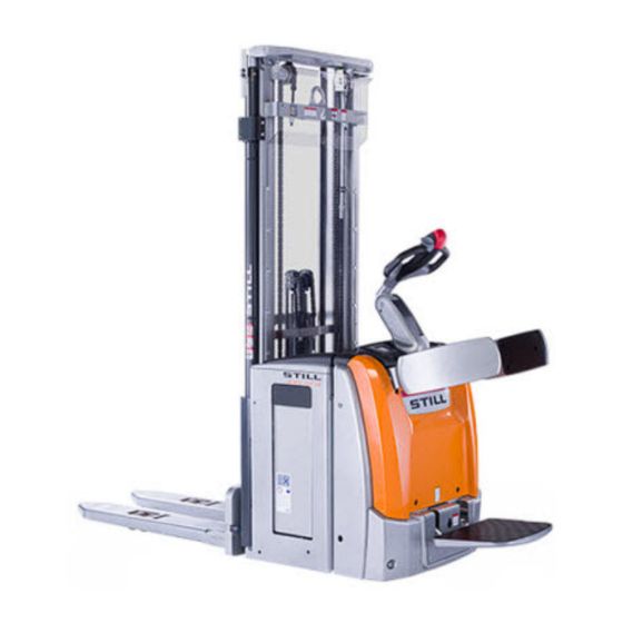
Pallet stacker
EXV 14 / 16 / 20
EXV 14i / 16i / 20i
EXV-SF 14 / 16 / 20
EXV-SF 14i / 16i / 20i
EXP 14 / 16 / 20
EXV 14D / 16D / 20D
EXV-SF 14D / 16D / 20D
0301 0303 0305 0323 0324
0325 0326 0327 0328 0329
0330 0331 0332 0333 0334
0335 0336 0337 0338 0339
0340
45758043443 EN - 12/2017
Advertisement
Table of Contents


Need help?
Do you have a question about the EXV 14D and is the answer not in the manual?
Questions and answers