Table of Contents
Advertisement
Quick Links
Quick Installation Guide
Moxa Industrial Managed Ethernet Switch
Moxa Americas:
Toll-free: 1-888-669-2872
Tel:
1-714-528-6777
Fax:
1-714-528-6778
Moxa Europe:
Tel:
+49-89-3 70 03 99-0
Fax:
+49-89-3 70 03 99-99
Moxa India:
Tel:
+91-80-4172-9088
Fax:
+91-80-4132-1045
TSN-G5000 Series
Version 1.0, June 2020
Technical Support Contact Information
www.moxa.com/support
2020 Moxa Inc. All rights reserved.
Moxa China (Shanghai office):
Toll-free: 800-820-5036
Tel:
+86-21-5258-9955
Fax:
+86-21-5258-5505
Moxa Asia-Pacific:
Tel:
+886-2-8919-1230
Fax:
+886-2-8919-1231
P/N: 1802050080011
*1802050080011*
Advertisement
Table of Contents

Related Manuals for Moxa Technologies TSN-G5000 Series


Summary of Contents for Moxa Technologies TSN-G5000 Series
- Page 1 TSN-G5000 Series Quick Installation Guide Moxa Industrial Managed Ethernet Switch Version 1.0, June 2020 Technical Support Contact Information www.moxa.com/support Moxa Americas: Moxa China (Shanghai office): Toll-free: 1-888-669-2872 Toll-free: 800-820-5036 Tel: 1-714-528-6777 Tel: +86-21-5258-9955 Fax: 1-714-528-6778 Fax: +86-21-5258-5505 Moxa Europe: Moxa Asia-Pacific:...
-
Page 2: Package Checklist
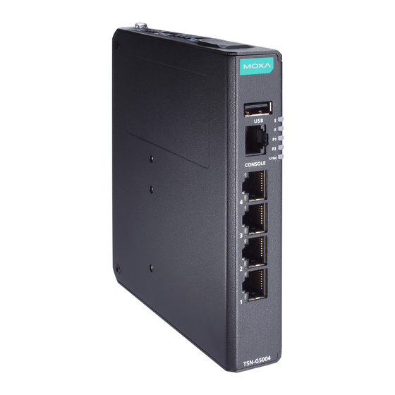
Package Checklist The TSN-G5000 Series is shipped with the following items. If any of these items are missing or damaged, please contact your customer service representative for assistance. • 1 TSN-G5000 Series industrial Ethernet switch • 1 RJ45 to RS-232 9-pin female console cable •... - Page 3 TSN-G5008-2GTXSFP 1. USB storage port (type A, currently disabled) 2. Console port (RJ45, RS-232) 3. LED indicators x 5 (STATE, FAULT, PWR1, PWR2, SYNC) 4. Ethernet ports x 4 (8 for TSN-G5008), (RJ45, 10/100/1000BaseT(X)) 5. LED indicator for 1000BaseT(X) 6. LED indicator for 10/100BaseT(X) 7.
- Page 4 Dimensions TSN-G5004 TSN-G5008-2GTXSFP Unit: mm (inch) - 4 -...
-
Page 5: Din-Rail Mounting
TSN-G5000 Series. Option 1 is the default type when shipped. Option 1 (default): When shipped, the metal DIN-rail mounting kit is fixed to the back panel of the TSN-G5000 Series. Mount the TSN-G5000 Series on the corrosion-free mounting rail that adheres to the EN 60715 standard. Suggested Installation Method Step 1—Insert the upper lip... -
Page 6: Default Installation
Option 2 (when side cabling is needed): The metal DIN-rail mounting kit can be fixed to the side panel of the TSN-G5000 Series. Mount the TSN-G5000 Series on the corrosion-free mounting rail that adheres to the EN 60715 standard. Default Installation... -
Page 7: Wall Mounting
For some applications, you will find it convenient to mount your TSN- G5000 Series on the wall, as illustrated below. Step 1—Remove the aluminum DIN-rail attachment plate from the TSN-G5000 Series rear panel, and then attach the wall mount plates, as shown in the diagram below. - 7 -... - Page 8 In order to ensure reliable operations, please make sure the operating temperature of the environment does not exceed the specifications. When mounting a TSN-G5000 Series with other operating units in a cabinet without forced ventilation, a minimum of 5 cm space on both the left and right of the switch is recommended.
-
Page 9: Wiring Requirements
ATTENTION Safety First! Be sure to disconnect the power cord before installing and/or wiring your Moxa TSN-G5000 Series. Calculate the maximum possible current in each power wire and common wire. Observe all electrical codes dictating the maximum current allowable for each wire size. -
Page 10: Wiring The Relay Contact
Wiring the Relay Contact The TSN-G5000 Series has one relay output for identifying when a specific event has occurred (i.e., fault; see below). This relay output uses the first contact out of the first 2-pin terminal on the TSN-G5000 Series' top panel. - Page 11 Wiring the Digital Input The TSN-G5000 Series has one set of digital inputs (DI). The DI consists of two contacts of the second 4-pin terminal block on the TSN- G5000 Series’ top panel, and the other 2 contacts are used for the power input 2 (PWR 2/P2).
- Page 12 Safety Extra-Low Voltages (SELV). The TSN-G5000 Series has two sets of power inputs–power input 1 (PWR 1/P1) and power input 2 (PWR 2/P2). The top view of the terminal block connector and the positions of the power inputs are shown below.
-
Page 13: Communication Connections
NOTE This port cannot be used for charging any devices. The TSN-G5000 Series has one USB storage port (type A connector; see the diagram below for pinout assignments) on the front panel. USB Port (Type A Connector) Pinouts... - Page 14 10/100/1000BaseT(X) Ethernet Port Connection The 10/100/1000BaseT(X) ports located on Moxa TSN-G5000 Switch’s front panel are used to connect to Ethernet-enabled devices. Most users will choose to configure these ports for Auto MDI/MDI-X mode, in which case the port’s pinouts are adjusted automatically depending on the type of Ethernet cable used (straight-through or cross-over), and the type of device (NIC-type or HUB/Switch-type) connected to the port.
- Page 15 RJ45 (8-pin) to RJ45 (8-pin) Cross-over Cable Wiring 100/1000Base-X Fiber Port The Fiber ports on the TSN-G5008-2GTXSFP are SFP type slots, which support both 100Base-FX and 1000Base-X speeds. Moxa provides complete transceiver models for various distance requirements. The concept behind the LC port and cable is quite straightforward. Suppose you are connecting devices I and II.
-
Page 16: Installing The Microsd Card
Installing the microSD card NOTE The microSD card function is currently disabled. The TSN-G5000 Series has a microSD slot located on the top panel of the switch. Remove the rubber cover first. Insert the microSD card into the slot. Make sure you insert the card in the correct direction. -
Page 17: Led Indicators
LED Indicators Color Status Description Per Device LED STATE Green System is running normally. Blinking 1. The system is booting up. 2. When pressing the reset button for 5 seconds to reset to factory default settings. System failed to initialize. FAULT Reserved. -
Page 18: Specifications
Specifications Interface RJ45 Ports 10/100/1000BaseT(X) Fiber Ports 100/1000BaseSFP Console Port RS-232 (RJ45) Relay Contact (Relay 1 normally open electromagnetic relays output Output) with current carrying capacity of 1 A @ 24 VDC Digital Input 1 isolated digital input: • +13 to +30 V for state “1” •... -
Page 19: Warranty
Shock IEC 60068-2-27 Freefall IEC 60068-2-32 Vibration IEC 60068-2-6 Note: Please check Moxa’s website for the latest certification status. Warranty Warranty Period 5-years Details See www.moxa.com/warranty ATTENTION This device complies with Part 15 of the FCC rules. Operation is subject to the following conditions: 1.
Need help?
Do you have a question about the TSN-G5000 Series and is the answer not in the manual?
Questions and answers