
Related Manuals for GEM SU60 SUMONDO


Summary of Contents for GEM SU60 SUMONDO
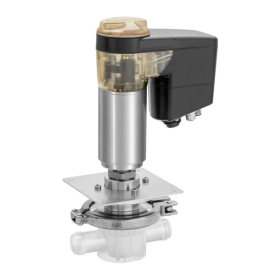
- Page 1 GEMÜ SU60 SUMONDO Motorized actuator for single-use valves Operating instructions further information webcode: GW-SU60...
- Page 2 All rights including copyrights or industrial property rights are expressly reserved. Keep the document for future reference. © GEMÜ Gebr. Müller Apparatebau GmbH & Co. KG 06.09.2021 GEMÜ SU60 SUMONDO 2 / 36 www.gemu-group.com...
-
Page 3: Table Of Contents
Network settings ........... 11.2 Connecting the network ........ 11.3 Resetting the network settings ..... 12 Commissioning ............ 13 Operation ............. 13.1 Operation on the device ........ 13.2 Operation via the web server ......www.gemu-group.com 3 / 36 GEMÜ SU60 SUMONDO... -
Page 4: General Information
Risk posed by sharp edges Flashing 1.3 Definition of terms Danger from potentially explosive atmosphere Working medium The medium that flows through the GEMÜ product. 1.4 Warning notes Wherever possible, warning notes are organised according to the following scheme: SIGNAL WORD... -
Page 5: Safety Information
14. Do not carry out any maintenance work and repairs not de- scribed in this document without consulting the manufac- turer first. In cases of uncertainty: 15. Consult the nearest GEMÜ sales office. www.gemu-group.com 5 / 36 GEMÜ SU60 SUMONDO... - Page 6 Moves actuator to the closed position Manual opera- Starting initialisation tion Actuator switched off (OFF mode) Manual opera- tion (on-site) Software update alternating On-site initialisa- tion (buttons) Remote initial- isation (via Di- gIn) GEMÜ SU60 SUMONDO 6 / 36 www.gemu-group.com...
-
Page 7: Description
Position unknown (e.g. 50%) interface 3.2 Description Initialisation The GEMÜ SU60 motorized hollow shaft actuator is based on technology that does not use brushes or sensors and there- fore guarantees high performance and a long service life. www.gemu-group.com 7 / 36... -
Page 8: Function
Do not use the product in potentially ● After use, the media wetted GEMÜ SUB unit can easily be dis- explosive zones. connected from the actuator and replaced. The actuator re- mains in the plant. -
Page 9: Order Data
Single-use actuator, motorized metal version 2 Diaphragm size Diaphragm size B 3 Diaphragm mounting 4 Voltage/Frequency 24 V DC 5 Control module OPEN/CLOSE, positioner and process controller 6 Actuator size Actuator size 0 www.gemu-group.com 9 / 36 GEMÜ SU60 SUMONDO... -
Page 10: Diaphragm Valve Body Sub
3/8" (DN 10) 4 Body configuration T body 5 Connection Hose barb 6 Body material PP-R, natural 7 Diaphragm material 8 Connection size 2 3/8" (DN 10) 9 Connection of spigot 2 Hose barb GEMÜ SU60 SUMONDO 10 / 36 www.gemu-group.com... -
Page 11: Technical Data
Ambient temperature: 0 — 40 °C Storage temperature: 0 — 40 °C 6.3 Pressure Operating pressure: 0 – 4.9 bar (Diaphragm size code B, C), 0 – 4.5 bar (Diaphragm size code D) www.gemu-group.com 11 / 36 GEMÜ SU60 SUMONDO... -
Page 12: Product Conformity
- USP Biological Reactivity Tests in vivo for Class VI, USP <88> - USP Physicochemical Tests for Plastics, USP <661> - USP Particulate Matter in Injections, USP <788>, USP <790> - Validation guide on request GEMÜ SU60 SUMONDO 12 / 36 www.gemu-group.com... -
Page 13: Mechanical Data
EMC Directive: 2014/30/EU 6.5 Mechanical data Service life: Diaphragm valve body 1000 switching cycles (according to GEMÜ product validation) (SUB): or max. 4.5 years from production date (1.5 years before steril- ization/3 years after sterilization) Protection class: Protection class IP 65 acc. to EN 60529 Actuating speed: Adjustable, max. - Page 14 Input resistance: 250 Ω Accuracy/linearity: ≤ ±0.3% of full flow Temperature drift: ≤ ±0.1% / 10°K Resolution: 12 bit Reverse battery protec- tion: Overload proof: Yes (up to ± 24 V DC) GEMÜ SU60 SUMONDO 14 / 36 www.gemu-group.com...
- Page 15 Switching voltage: Supply voltage Switching current: ≤ 0.1 A Drop voltage: Max. 2.5 V DC at 0.1 A Overload proof: Yes (up to ± 24 V DC) Short-circuit proof: Pull-Down resistance: 120 kΩ www.gemu-group.com 15 / 36 GEMÜ SU60 SUMONDO...
- Page 16 255.255.252.0 alterable via web browser Port: Supported function Code Dezimal Code Hex Function codes: 0x03 Read Holding Registers 0x04 Read Input Registers 0x06 Write Single Register 0x10 Write Multiple Registers 0x17 Read/Write Multiple Registers GEMÜ SU60 SUMONDO 16 / 36 www.gemu-group.com...
-
Page 17: Dimensions
125.5 160.0 184.1 34.7 91.0 62.0 1'' (DN 25) 3/4'' (DN 20), 272.9 249.1 210.3 10.0 91.0 125.5 160.0 184.1 34.7 91.0 62.0 1'' (DN 25) Dimensions in mm, MG = diaphragm size www.gemu-group.com 17 / 36 GEMÜ SU60 SUMONDO... -
Page 18: Body Dimensions
ØD Connection type hose barb (code HB) øD 3/8” (DN 10) 64.0 33.3 22.3 48.0 58.0 10.0 1/2” (DN 15) 64.0 33.3 22.3 55.8 66.8 10.0 Dimensions in mm, MG = diaphragm size GEMÜ SU60 SUMONDO 18 / 36 www.gemu-group.com... - Page 19 3/4” (DN 20) 91.6 58.5 38.0 139.0 1” (DN 25) 91.6 58.5 39.5 139.0 Dimensions in mm, MG = diaphragm size 1) Connection Code CA: Clamp connection similar to ASME-BPE Code HB: Hose barb www.gemu-group.com 19 / 36 GEMÜ SU60 SUMONDO...
- Page 20 35.3 128.0 82.0 18.0 1” (DN 25) 91.0 60.0 35.3 140.0 88.0 18.0 Dimensions in mm, MG = diaphragm size 1) Connection Code CA: Clamp connection similar to ASME-BPE Code HB: Hose barb GEMÜ SU60 SUMONDO 20 / 36 www.gemu-group.com...
-
Page 21: Connection Dimensions
1” (DN 25) 28.0 24.7 11.5 25.3 30.8 3/4” (DN 20) 22.0 21.4 19.0 25.0 1” (DN 25) 28.0 22.2 11.5 25.4 30.8 Dimensions in mm, MG = diaphragm size Tolerance ± 0.2 mm www.gemu-group.com 21 / 36 GEMÜ SU60 SUMONDO... -
Page 22: Electrical Connection
Relay output K2, make contact Pin PE Function earth 8.2 Connection X2 5-pin M12 built-in socket, D-coded Signal name Pin 1 Tx + (Ethernet) Pin 2 Rx + (Ethernet) Pin 3 Tx - (Ethernet) GEMÜ SU60 SUMONDO 22 / 36 www.gemu-group.com... -
Page 23: Manufacturer's Information
"Technical data"). ● maximum permitted pressures caused by pressure 4. Do not store solvents, chemicals, acids, fuels or similar surges (water hammer). fluids in the same room as GEMÜ products and their spare parts. CAUTION Leakage ▶ Emission of dangerous materials. -
Page 24: Assembling The Motorized Actuator In The Housing
12. Lay piping so that the product is protected against trans- verse and bending forces, and also from vibrations and tension. 13. Only install the product between matching aligned pipes. 14. Optional installation position. Fig. 5: Borehole pattern for housing (housing not included) GEMÜ SU60 SUMONDO 24 / 36 www.gemu-group.com... -
Page 25: Disassembling The Motorized Stainless Steel Actuator - Housing
3. Undo the bolts between the mounting plate 4 and the housing 5. 4. Pull the motorized actuator A inwards through the recess of the housing 5 (in the direction of the actuator housing). www.gemu-group.com 25 / 36 GEMÜ SU60 SUMONDO... -
Page 26: Assembling The Single-Use Diaphragm Valve Body On The Motorized Stainless Steel Actuator
▶ Depressurize the plant before disas- sembly. NOTICE ▶ The single-use diaphragm valve body 1 ▶ The single-use diaphragm valve body can only be used cannot be used after disassembly. once and must be disposed of after use. GEMÜ SU60 SUMONDO 26 / 36 www.gemu-group.com... -
Page 27: Network Connection
2. Press and hold down the "OPEN" button 9 for at least 8 s. ð LED 1 flashes fast in blue. 3. Press the "INIT/CLOSE" button 10. ð Network settings are reset in the default settings. www.gemu-group.com 27 / 36 GEMÜ SU60 SUMONDO... -
Page 28: Commissioning
13.1.1 Moving the valve to the open position 1. Move the "ON-Site" DIP switch 8 to the "ON" position (see “Buttons for on-site control“, page 6). ð Control on the device is activated. 2. Press the "OPEN" button 9. GEMÜ SU60 SUMONDO 28 / 36 www.gemu-group.com... - Page 29 8. Ensure correct positioning of the O-ring. 9. Push actuator 12 into the groove provided for this pur- pose. 10. Turn housing cover 3 anticlockwise until it stops. ð The actuator cover is closed. 11. Reconnect the power supply. www.gemu-group.com 29 / 36 GEMÜ SU60 SUMONDO...
-
Page 30: Troubleshooting
Replace the valve body/actuator ator flange, clamp and valve body Body of the GEMÜ product is leaking Body of the GEMÜ product is faulty Check the body of the GEMÜ product for potential damage, replace the body if ne- cessary Incorrect installation... - Page 31 14 Troubleshooting Error Possible cause Troubleshooting LED 1 and 2 are flashing yellow and red No calibration Contact GEMÜ simultaneously Internal error Contact GEMÜ www.gemu-group.com 31 / 36 GEMÜ SU60 SUMONDO...
-
Page 32: Inspection And Maintenance
3. Shut off plant or plant component. 4. Secure plant or plant component against recommission- ing. 5. Depressurize the plant or plant component. 6. Actuate GEMÜ products which are always in the same po- sition four times a year. CAUTION Use of incorrect spare parts! ▶... -
Page 33: Declaration Of Incorporation According To 2006/42/Ec (Machinery Directive)
19 Declaration of Incorporation according to 2006/42/EC (Machinery Directive) 19 Declaration of Incorporation according to 2006/42/EC (Machinery Directive) www.gemu-group.com 33 / 36 GEMÜ SU60 SUMONDO... -
Page 34: Manufacturer's Declaration According To 2014/68/Eu (Pressure Equipment Directive)
20 Manufacturer's declaration according to 2014/68/EU (Pressure Equipment Directive) 20 Manufacturer's declaration according to 2014/68/EU (Pressure Equipment Directive) GEMÜ SU60 SUMONDO 34 / 36 www.gemu-group.com... -
Page 35: Declaration Of Conformity According To 2014/30/Eu (Emc Directive)
21 Declaration of conformity according to 2014/30/EU (EMC Directive) 21 Declaration of conformity according to 2014/30/EU (EMC Directive) www.gemu-group.com 35 / 36 GEMÜ SU60 SUMONDO... - Page 36 Subject to alteration GEMÜ Gebr. Müller Apparatebau GmbH & Co. KG *88775842* Fritz-Müller-Straße 6-8, 74653 Ingelfingen-Criesbach, Germany 09.2021 | 88775842 Phone +49 (0) 7940 1230 · info@gemue.de www.gemu-group.com...
Need help?
Do you have a question about the SU60 SUMONDO and is the answer not in the manual?
Questions and answers