
Subscribe to Our Youtube Channel
Related Manuals for CYP MED-AS60


Summary of Contents for CYP MED-AS60
- Page 1 MED-AS60 Multi-Input Switcher with Multi-Window Display Operation Manual Operation Manual...
- Page 2 ® registered trademarks of HDMI licensing Administrator, Inc.
- Page 3 DISCLAIMERS The information in this manual has been carefully checked and is believed to be accurate. Cypress Technology assumes no responsibility for any infringements of patents or other rights of third parties which may result from its use. Cypress Technology assumes no responsibility for any inaccuracies that may be contained in this document.
- Page 4 SAFETY PRECAUTIONS Please read all instructions before attempting to unpack, install or operate this equipment and before connecting the power supply. Please keep the following in mind as you unpack and install this equipment: • Always follow basic safety precautions to reduce the risk of fire, electrical shock and injury to persons.
-
Page 5: Table Of Contents
CONTENTS 1. Introduction ...............1 2. Applications ..............1 3. Package Contents ............1 4. System Requirements ............2 5. Features................2 6. Operation Controls and Functions .........3 6.1 Front Panel ..............3 6.2 Rear Panel..............4 6.3 RS-232 Pinout and Defaults .........5 6.4 Software Control ............6 6.4.1 Software Installation ..........6 6.4.2 Device Connection ..........7 6.4.3 Settings Tab ............8... -
Page 6: Introduction
1. INTRODUCTION This Multi-Input Switcher with Multi-Window Display unit supports all of the most common professional video formats used by medical devices at resolutions up to 1080p@60Hz (4:4:4, 12-bit). Available inputs include: 4 HDMI, 2 SDI, 2 RGBHV (VGA), and 2 composite video. After connecting multiple medical device signal sources, this unit converts all of the signals to HDMI to allow the information to be integrated together within a variety of convenient multi-window (up to 4 simultaneous windows) preset... -
Page 7: System Requirements
4. SYSTEM REQUIREMENTS • HDMI, VGA, SDI, and composite video source equipment such as video cameras, medical equipment, or set-top boxes. • HDMI receiving equipment such as HDTVs, monitors or audio amplifiers. • Windows 10 or later PC for configuration and control. •... -
Page 8: Operation Controls And Functions
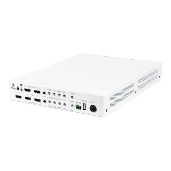
6. OPERATION CONTROLS AND FUNCTIONS 6.1 Front Panel HDMI OUT B CVBS HDMI CAM 2 SERVICE DC 24V LINK RS-232 GROUP SELECT PORT TX RX TX RX HDMI OUT A CVBS HDMI CAM 1 IP A/B Button & LEDs: Press this button to toggle between monitoring HDMI output A or B on the IP output. -
Page 9: Rear Panel
6.2 Rear Panel CVBS SDI IN HDMI IN CAM 2 HDMI IN CAM 1 SDI IN CVBS GROUP 1: SDI IN Port: Connect to SDI source equipment such as a video camera, medical equipment, or set-top box. Note: SDI audio is not supported. HDMI IN Port: Connect to HDMI source equipment such as a video camera, medical equipment, or set-top box. -
Page 10: Rs-232 Pinout And Defaults
6.3 RS-232 Pinout and Defaults Serial Port Default Settings Baud Rate 19200 Data Bits Parity Bits None Stop Bits Flow Control None 3-pin Terminal Block... -
Page 11: Software Control
6.4 Software Control This unit’s dedicated control software provides complete control over the unit via the RS-232 terminal block connection. This software provides control over source switching, multiview layout selection, IP output monitoring selection, output resolutions, primary input type selection, audio source selection, and per-window proc-amp settings. -
Page 12: Device Connection
6.4.2 Device Connection By default, when the software starts, it will not be connected to a unit, and a blank starter screen will be displayed. To connect to a unit, switch to the System Tab and use the dropdowns to select the correct COM port and baud rate for connecting to the preferred unit. -
Page 13: Settings Tab
6.4.3 Settings Tab This tab provides convenient access to control over all input, output, and display configuration functions of the unit. At the top of the page is a Sync icon ( ) that can be clicked on to force the software to resynchronize with the unit, if necessary. - Page 14 „ Rename Output: To rename either output, double click on the output’s name to open the “Rename” dialog window. Type in the preferred new name, up to 32 characters long, and then click “OK”. „ Multiview Window Color Settings: To adjust the brightness, contrast, or saturation of a multiview window, click on the Color Settings icon ( ) and a window will pop up.
-
Page 15: System Tab
6.4.4 System Tab Once connected to a unit, this tab provides access to basic unit details such as model name, serial number, and firmware versions, as well as a way to reset the unit to its factory defaults, update the primary MCU’s firmware, and disconnect from the unit. -
Page 16: Serial Commands
6.5 Serial Commands COMMAND Description and Parameters help Show the full command list. help N1 Show details about the specified command. N1 = {Command} ? Show the full command list. ? N1 Show details about the specified command. N1 = {Command} get fw ver... - Page 17 COMMAND Description and Parameters get out N1 name Show the name of the specified output. Available values for N1: [HDMI output A] [HDMI output B] get out name list List the names of all outputs on the unit. set out N1 timing N2 Set the output resolution to use for the specified output.
- Page 18 COMMAND Description and Parameters get out N1 timing Show the current resolution used by the specified output. Available values for N1: [HDMI output A] [HDMI output B] set audio out N1 route N2 Route the specified audio input to the specified audio output. Available values for N1: [HDMI output A] [HDMI output B]...
- Page 19 COMMAND Description and Parameters get out N1 window N2 contrast Show the current contrast level for the specified window on the specified output. Available values for N1: [HDMI output A] [HDMI output B] N2 = 1~4 [Window number] set out N1 window N2 brightness N3 Set the brightness level for the specified window on the specified output.
- Page 20 COMMAND Description and Parameters get out N1 window N2 saturation Show the current saturation level for the specified window on the specified output. Available values for N1: [HDMI output A] [HDMI output B] N2 = 1~4 [Window number] set out N1 osd info display N2 Enable or disable the info OSD for the specified output.
- Page 21 COMMAND Description and Parameters get group N1 in N2 name Show the current name of the specified input within the specified group. Available values for N1: [Group 1] [Group 2] Available values for N2: [SDI input] [HDMI input] [VGA input] [CVBS input] set in N1 name N2...
- Page 22 COMMAND Description and Parameters get group N1 route Show which input is currently active within the specified group. Available values for N1: [Group 1] [Group 2] set all group route N1 Set the specified input type as active within both groups. Available values for N1: [SDI input] [HDMI input]...
- Page 23 COMMAND Description and Parameters set out N1 window layout mode N2 Set the unit’s window layout mode for the specified output. Available values for N1: [HDMI output A] [HDMI output B] Available values for N2: [Quad split, equal division] [PiP, Cam 1 primary, Cam 2 secondary] [PiP, Cam 1 primary, Group 1 secondary] [PiP, Cam 1 primary, Group 2 secondary] [PiP, Cam 2 primary, Cam 1 secondary]...
- Page 24 COMMAND Description and Parameters set ToIP route N1 Set which output’s content to also route to the “IP” HDMI output. Available values for N1: [HDMI output A] [HDMI output B] get ToIP route Show the HDMI output that is currently monitored by the “IP” HDMI output.
-
Page 25: Connection Diagram
7. CONNECTION DIAGRAM PC/Laptop HDMI TV/Display HDMI TV/Display PC/Laptop HDMI TV/Display HDMI TV/Display HDMI TV/Display RS-232 HDMI HDMI HDMI HDMI HDMI Output Output Output Output Output HDMI OUT B CVBS HDMI CAM 2 SERVICE DC 24V PORT GROUP SELECT LINK RS-232 TX RX TX RX... -
Page 26: Specifications
8. SPECIFICATIONS 8.1 Technical Specifications HDMI Bandwidth 6.75Gbps VGA Bandwidth 165MHz SDI Bandwidth 2.970Gbps Input Ports 4×HDMI (Type-A) 2×3G-SDI (BNC) 2×VGA (5-BNC) 2×CVBS (BNC) Output Ports 5×HDMI (Type-A) Control Port 1×RS-232 (3-pin Terminal Block) Service Port 1×USB 2.0 (Type-A) Baud Rate 19200 Power Supply 24V/2.7A DC... -
Page 27: Video Specifications
8.2 Video Specifications Input Output Supported Resolutions (Hz) HDMI CVBS HDMI 720×400p@70/85 640×480p@60/72/75/85 720×480i@60 720×480p@60 720×576i@50 ... -
Page 28: Audio Specifications
Input Output Supported Resolutions (Hz) HDMI CVBS HDMI 2560×1440p@60RB 2560×1600p@60RB 2048×1080p@24/25/30 2048×1080p@50/60 3840×2160p@24/25/30 3840×2160p@50/60 (4:2:0) ... -
Page 29: Cable Specifications
8.4 Cable Specifications 480i/p 1080p 4K30 4K60 (4:4:4) (4:4:4) Cable Length 8-bit 8-bit 8-bit 8-bit High Speed HDMI Cable HDMI Input HDMI Output Coaxial Cable (75Ω) SDI Input 400m CVBS Input VGA Cable (5-BNC) VGA Input ... -
Page 30: Acronyms
9. ACRONYMS ACRONYM COMPLETE TERM 3G-SDI 3 Gigabit Serial Digital Interface ASCII American Standard Code for Information Interchange Audio/Video Receiver or Recorder Command-Line Interface COAX Coaxial Communication Digital Visual Interface EDID Extended Display Identification Data Gbps Gigabits per second Graphical User Interface High-Definition HDCP High-bandwidth Digital Content Protection... - Page 31 ACRONYM COMPLETE TERM 4K UHD 4K Ultra-High-Definition (18Gbps max) UHDTV Ultra-High-Definition Television Universal Serial Bus Video Graphics Array WUXGA (RB) Widescreen Ultra Extended Graphics Array (Reduced Blanking) Extended Graphics Array Ω...
- Page 32 CYPRESS TECHNOLOGY CO., LTD. www.cypress.com.tw...
Need help?
Do you have a question about the MED-AS60 and is the answer not in the manual?
Questions and answers