Advertisement
Quick Links
Advertisement

Subscribe to Our Youtube Channel
Related Manuals for Teknik 5422378


Summary of Contents for Teknik 5422378
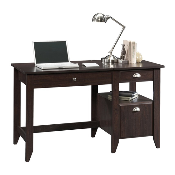
- Page 1 You could totally write a novel on this. Sit Stand Desk Model 5422378...
- Page 2 Table of Contents Assembly Tools Required Part Identifi cation No. 2 Phillips Screwdriver Tip Shown Actual Size Hardware Identifi cation Assembly Steps 6-38 Hammer Not actual size Français 39-43 Español 44-48 Safety 49-50 Warranty RIGHT END (1) LARGE BOTTOM (1) REAR LEG (1) LEFT END (1) BACK STRETCHER (1)
- Page 3 Now you know Part Identifi cation our ABCs. å While not all parts are labeled, some of the parts will have a label or an inked letter on the edge to help distinguish similar parts from each other. Use this part identifi cation to help identify similar parts. D716 D716 Page 3...
- Page 4 Hardware Identifi cation 40CA CABINET RIGHT - 1 40CB CABINET LEFT - 1 40CC DRAWER RIGHT -1 40CD DRAWER LEFT - 1 (EXTENSION SET SHOWN SEPARATED) EXTENSION RAIL - 2 EXTENSION SLIDE - 2 10A SLIDE CAM - 4 FILE GLIDE - 2 35MA 35MC ®...
- Page 5 Hardware Identifi cation å Screws are shown actual size. You may receive extra hardware with your unit. BLACK 9/16" LARGE HEAD SCREW - 28 3S GOLD 5/16" FLAT HEAD SCREW - 16 BLACK 1/2" FLAT HEAD SCREW - 4 12S BROWN 1" FLAT HEAD SCREW - 2 30S BLACK 1-9/16"...
- Page 6 Step 1 Assemble your unit on a carpeted fl oor or on the empty å carton to avoid scratching your unit or the fl oor. To begin assembly, push sixteen SAUDER TWIST-LOCK® å FASTENERS (7F) into the large holes in the RIGHT END (A), UPRIGHT (E), SHELF (L), PEDESTAL BOTTOM (U), and PEDESTAL BACK (V).
- Page 7 Step 2 Push thirty-seven HIDDEN CAMS (1F) into the ENDS (A and B), å BACK STRETCHER (G), UPRIGHT (E), STRETCHER (H), LONG Some assembly BACK (I), SMALL BACK (J), FRONT (K), PEDESTAL (and snacks) required. ENDS (M and N), and PEDESTAL BACK (V). Arrow (37 used) Arrow...
- Page 8 Step 3 Turn thirty-seven CAM SCREWS (8F) into the LEGS (O, P, Q, R, S, and T), å LEFT END (B), and STRETCHER (H). (37 used) Page 8...
- Page 9 Step 4 Turn two BLACK 9/16" FLAT HEAD SCREWS (32S) into å the PEDESTAL RIGHT END (N) until the shoulders of the SCREWS rest on the surface of the PEDESTAL RIGHT END. NOTE: Do not overtighten the SCREWS. å Slide the END MOLDING (Z) onto the PEDESTAL RIGHT å...
- Page 10 Step 5 Fasten the RIGHT END (A) and PEDESTAL RIGHT å END (N) to the RIGHT REAR LEG (T). Tighten four HIDDEN CAMS. Fasten the RIGHT FRONT LEG (Q) to the RIGHT END (A) and å PEDESTAL RIGHT END (N). Tighten four HIDDEN CAMS. Surface with HIDDEN CAMS Angled edge Edge with...
- Page 11 Step 6 Fasten the CABINET RIGHT (40CA) to the RIGHT END (A) å and the CABINET LEFT (40CB) to the UPRIGHT (E). Use Don't worry. It isn't four GOLD 5/16" FLAT HEAD SCREWS (3S) through Rome. This can be built holes #1 and #3.
- Page 12 Step 7 Separate the EXTENSION SLIDES (35MC) from the EXTENSION RAILS (35MA) as shown in the upper diagram below. Be å prepared, the parts are greasy. Fasten the EXTENSION RAILS (35MA) to the PEDESTAL RIGHT END (N) and PEDESTAL LEFT END (M). Use four GOLD å...
- Page 13 Step 8 First, fi ll the holes in the LEFT REAR LEG (S) 1/4 to 1/2 full å with GLUE (177M). Then, insert the WOOD DOWELS (15F) into the holes. Wipe away the excess GLUE. 177M Now, fi ll the holes in the LEFT END (B) and STRETCHER (H) 1/4 å...
- Page 14 Step 9 Fasten the LONG BACK (I) to the LEFT END (B). Tighten å two HIDDEN CAMS. Curved edge S u r f a c w i t h H I D D E N Page 14...
- Page 15 Step 10 First, fi ll the hole in the STRETCHER (H) 1/4 to 1/2 full å with GLUE (177M). Then, insert the WOOD DOWEL (15F) into the hole. Wipe away the excess GLUE. 177M Now, fi ll the hole in the BACK STRETCHER (G) 1/4 to 1/2 å...
- Page 16 Step 11 Fasten the UPRIGHT (E) and PEDESTAL LEFT END (M) to the REAR LEG (R). å Tighten four HIDDEN CAMS. Roller end i t h f a c S u r D E N H I D These two small holes must be here.
- Page 17 Step 12 Fasten the BACK LEG (R) to the LONG BACK (I). Use two BROWN 1" FLAT å HEAD SCREWS (12S). Fasten the PEDESTAL LEFT END (M) to the BACK STRETCHER (G). Use two å BLACK 1-15/16" FLAT HEAD SCREWS (113S). 113S BLACK 1-15/16"...
- Page 18 Step 13 NOTE: Position the TWIST-LOCK® FASTENERS exactly as shown. å How to use the SAUDER TWIST-LOCK® FASTENER Insert the dowel end of eight SAUDER TWIST-LOCK® å 1. Insert the dowel end of the FASTENER into the hole of the adjoining part. FASTENERS (7F) into the LEFT END (B), LONG BACK (I), and UPRIGHT (E).
- Page 19 Step 14 First, fi ll the holes in the short edges of the FRONT (K) 1/4 to 1/2 å full with GLUE (177M). Then, insert two WOOD DOWELS (15F) into the holes. Wipe away the excess GLUE. 177M Now, fi ll the holes in the FRONT LEGS (O and P) a 1/4 to 1/2 å...
- Page 20 Step 15 First, fi ll the holes in the short edge of the LEFT END (B) and å STRETCHER (H) 1/4 to 1/2 full with GLUE (54M). Then, insert a WOOD DOWEL (15F) into each hole. Wipe away the excess GLUE. Now, fi...
- Page 21 Step 16 Turn three CORD CLIPS (9P) into the holes in the LARGE BOTTOM (F). å Fasten the SMALL UPRIGHT (AA) to the LARGE BOTTOM (F). å Just breathe. Use three BLACK 1-15/16" FLAT HEAD SCREWS (113S). It's going to be ok. Fasten the SMALL BACK (J) to the REAR LEG (R).
- Page 22 Step 17 Fasten the PEDESTAL BOTTOM (U) and SHELF (L) to the å PEDESTAL BACK (V). Tighten four TWIST-LOCK® FASTENERS. S u r f a c i t h E R S I S T - L O S u r ®...
- Page 23 Step 18 Fasten the SHELF (L) and PEDESTAL BOTTOM (U) to å the PEDESTAL LEFT END (M). Tighten four TWIST-LOCK® FASTENERS. Fasten the PEDESTAL BACK (V) to the REAR LEG (R). å Tighten two HIDDEN CAMS. Page 23...
- Page 24 Step 19 Fasten the RIGHT REAR LEG (T) to the PEDESTAL BACK (V) and å SMALL BACK (J). Tighten four HIDDEN CAMS. Fasten the PEDESTAL RIGHT END (N) to the PEDESTAL BOTTOM (U) å and SHELF (L). Tighten four TWIST-LOCK® FASTENERS. Page 24...
- Page 25 Step 20 Carefully stand your unit upright. å Fasten the TOP (C) to the RIGHT END (A) and UPRIGHT (E). å Tighten four TWIST-LOCK® FASTENERS. These edges must be even. Page 25...
- Page 26 Step 21 Fasten three ANGLE BRACKETS (5G) to the LONG BACK (I), å LEFT END (B), SMALL UPRIGHT (AA) and FRONT (K). Use six BLACK 9/16" LARGE HEAD SCREWS (1S). Fasten a METAL BRACKET (2G) to the LEFT END (B) and å...
- Page 27 Step 22 Turn a CORD CLIP (9P) into the hole in the LIFT-TOP (D). å Fasten two LONG PULLS (21K) to the LIFT-TOP (D). Use four å BLACK 1/2" FLAT HEAD SCREWS (11S). BLACK 1/2" FLAT HEAD SCREW (4 used in this step) Page 27...
- Page 28 Step 23 Fasten the LIFT TABLE MECHANISMS (141M) to the å LIFT-TOP (D). Use eight BLACK 9/16" LARGE HEAD SCREWS (1S). NOTE: Be sure to fasten the LIFT TABLE MECHANISMS å exactly as shown. 141M BLACK 9/16" LARGE HEAD SCREW (8 used in this step) 141M Page 28...
- Page 29 Step 24 Fasten the SUPPORT BRACKETS (37G) to the LIFT å TABLE MECHANISMS (141M). Use four WASHERS (13M), four NUTS (24M), and four BLACK 3/4" MACHINE SCREWS (92S). 141M 141M BLACK 3/4" MACHINE SCREW (4 used in this step) Page 29...
- Page 30 Step 25 IMPORTANT: You will need someone's help in this step. å Fasten the LIFT TABLE MECHANISMS (141M) to the LEFT END (B) å Hey! It's starting to look and SMALL UPRIGHT (AA). Use twelve BLACK 9/16" LARGE like something! HEAD SCREWS (1S).
- Page 31 Step 26 Fasten the LIFT-TOP STRETCHER (X) to the SUPPORT å BRACKETS (37G) on the LIFT TABLE MECHANISMS (141M). Use four WASHERS (13M), four NUTS (24M), and four BLACK 1-1/4" MACHINE SCREWS (93S). BLACK 1-1/4" MACHINE SCREW (4 used in this step) 141M 141M Page 31...
- Page 32 Step 27 The tabs should insert freely into the slots. Gently tilt the DRAWER SIDES side to side until the tabs slip into the slots. BLACK 7/8" LARGE HEAD SCREW (4 used in this step) These holes must line up. Groove Fasten the LARGE DRAWER BOX FRONT (W) to the Insert the LARGE DRAWER SIDES (D14 and D15)
- Page 33 Step 28 The tabs should insert freely into the slots. Gently tilt the DRAWER SIDES side to side until the tabs slip into the slots. BLACK 7/8" LARGE HEAD SCREW (2 used in this step) Groove Fasten the SMALL DRAWER BOX FRONT (Y) to the Insert the SMALL DRAWER SIDES (D20 and D21) å...
- Page 34 Step 29 Insert a SLIDE CAM (10A) into the LARGE DRAWER SIDES (D14 and D15). å Fasten the EXTENSION SLIDES (35MC) to the LARGE DRAWER SIDES (D14 and D15). å Use four GOLD 5/16" FLAT HEAD SCREWS (3S) through holes #1 and #3. NOTE: The screw head in the CAM must be visible through the slotted hole in the SLIDE.
- Page 35 Step 30 Insert a SLIDE CAM (10A) into the SMALL DRAWER SIDES (D20 and D21). å Fasten the DRAWER RIGHT (40CC) and DRAWER LEFT (40CD) to the å DRAWER SIDES (D20 and D21). Use four GOLD 5/16" FLAT HEAD SCREWS (3S) through holes #2 and #4. NOTE: The screw head in the CAM must be visible through the slotted hole å...
- Page 36 Step 31 Fasten the PULLS (7K) to the DRAWER FRONTS (BB and CC). å Use four GRAY 1-3/8" MACHINE SCREWS (39S). Push a FILE GLIDE (4B) onto the top edge of each LARGE å DRAWER SIDE (D14 and D15). GRAY 1-3/8" MACHINE SCREW (4 used in this step) Page 36...
- Page 37 Step 32 Insert the GROMMET (10P) into the large hole in the LARGE BOTTOM (F). å Using your hammer, gently tap a CAM COVER (12P) onto each HIDDEN CAM. å To insert the small drawer into your unit, tip the front of the drawer down and drop the rollers on the drawer behind the å...
- Page 38 Step 33 To make adjustments to the small drawer, loosen SCREW #4 in the SLIDES a 1/4 turn, then turn the CAM clockwise or å counter-clockwise. Notice how the drawer raises or lowers as you turn the CAM. The higher the screw in the oblong hole, the higher your drawer front will be.
- Page 39 WARNING Please use your furniture correctly and safely. Improper use can cause safety hazards, or damage to your furniture or household items. Carefully read the following chart. Look out for: What can happen: How to avoid the problem: • Overloaded shelves or drawers. •...
Need help?
Do you have a question about the 5422378 and is the answer not in the manual?
Questions and answers