Table of Contents
Advertisement
Quick Links
2
5
V
A
/
2
2
5
V
A
/
2
K
K
3
4
0
0
V
3
4
0
0
V
X
A
C
X
A
C
W
I
T
H
T
R
U
E
O
W
I
T
H
T
R
U
E
O
User Guide
Release 1.5, February 2014
G
AMATRONIC
17 Hartom St., PO Box 45029, Jerusalem 91450, Israel
Tel: +972-2-588-8222
Email: info@gamatronic.co.il
SA25
5
W
5
W
K
D
O
U
B
K
D
O
U
B
(
G
a
m
a
t
r
o
n
i
c
c
a
t
.
n
o
.
1
0
1
(
G
a
m
a
t
r
o
n
i
c
c
a
t
.
n
o
.
1
0
1
-
-
N
L
I
N
E
B
A
T
T
E
R
N
L
I
N
E
B
A
T
T
E
R
E
I
LECTRONIC
NDUSTRIES
Fax: +972-2-582-8875
Website: www.gamatronic.com
-
-
L
E
C
O
N
V
E
R
S
L
E
C
O
N
V
E
R
S
L
D
6
1
-
4
0
5
)
S
L
D
6
1
-
4
0
5
)
Y
Y
L
.
TD
U
P
S
U
P
S
I
O
N
S
I
O
N
Advertisement
Table of Contents

Related Manuals for Gamatronic MEGA V2 SA25


Summary of Contents for Gamatronic MEGA V2 SA25
- Page 1 SA25 User Guide Release 1.5, February 2014 AMATRONIC LECTRONIC NDUSTRIES 17 Hartom St., PO Box 45029, Jerusalem 91450, Israel Tel: +972-2-588-8222 Fax: +972-2-582-8875 Email: info@gamatronic.co.il Website: www.gamatronic.com...
- Page 2 Gamatronic is not liable for and the Purchaser waives any right of action it has or may have against Gamatronic for any consequential or special damages arising out of any breach of warranty, and for any damages that the Purchaser may claim for damage to any property or injury or death to any person arising out of its purchase or the use, operation or maintenance of the subject product.
-
Page 3: Table Of Contents
ETERMINING THE CURRENT AUTOMATIC RESTART SETTING ............45 HANGING THE AUTOMATIC RESTART STATUS ..................... 47 ISCELLANEOUS UNCTIONS 10.1 M ............47 ANUALLY ENTERING OR LEAVING BYPASS MODE 10.1.1 Entering bypass mode manually ..............47 User Guide: MEGA V2 SA25, Release 1.5... - Page 4 EMOVE THE FEET 33: R ....... 35 IGURE EMOVE THE SCREWS ON RIGHT SIDE SCREWS ON LEFT SIDE 34: R ....... 36 IGURE EAR VIEW OF THE SHOWING CABLE ENTRY HOLES AT REAR User Guide: MEGA V2 SA25, Release 1.5...
- Page 5 ATTERY LIFETIME VS ENVIRONMENTAL TEMPERATURE 2: M ..................... 22 ABLE AIN MENU OPTIONS 3: O .................. 27 ABLE UTSTANDING ALARM MESSAGES 4: L ......................29 ABLE OG MESSAGES 5: R ................31 ABLE ECOMMENDED CABLE DIAMETERS User Guide: MEGA V2 SA25, Release 1.5...
-
Page 6: Conventions Used In This Book
• Abbreviations and notational conventions are in most instances as per the IEEE Standards Style Manual. User Guide: MEGA V2 SA25, Release 1.5... -
Page 7: Safety Considerations
Gamatronic Electronic Industries Ltd. AFETY CONSIDERATIONS The MEGA V2 SA25 UPS system is designed for industrial applications and harsh environments. Nevertheless the Mega V2 SA25 UPS system is a sophisticated power system and should be handled with appropriate care, following these guidelines. - Page 8 HEREFORE IT IS STRICTLY FORBIDDEN TO CONNECT THIS SYSTEM TO THE AC POWER SOURCE WITHOUT A NEUTRAL NULL CONDUCTOR AILURE TO USE A NEUTRAL CONDUCTOR MAY CAUSE PERMANENT DAMAGE TO THE SYSTEM viii User Guide: MEGA V2 SA25, Release 1.5...
-
Page 9: Introduction
Over time, these irregularities shorten the life of equipment and components. The efficiency of Mega V2 SA25 thus helps to extend the life of your equipment, even during normal use when the input power is constant and continuous. -
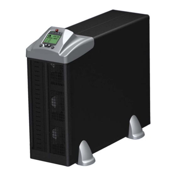
Page 10: Figure 1: The Mega
Gamatronic Electronic Industries Ltd. Figure 1: The Mega V2 SA25 Figure 2: Block diagram of the Mega V2 SA25 User Guide: MEGA V2 SA25, Release 1.5... -
Page 11: Major Parts Of The Mega V2 Sa25
BATTERY The Mega V2 SA25 battery bank is used as a backup in the event that the utility ac input fails. The batteries are housed in an external cabinet next to the Mega V2 SA25 cabinet. Batteries are charged by the rectifier, which supplies both the inverter and the battery charger. -
Page 12: Perating Modes
Gamatronic Electronic Industries Ltd. PERATING MODES The Mega V2 SA25 is installed between the power mains and your load devices, and supplies ac electrical power to your equipment. The Mega V2 SA25 has three automatic modes of operation: • Normal mode •... -
Page 13: Battery Mode
The duration of the battery operation is determined by the load demand and battery capacity. Figure 4: Battery mode display User Guide: MEGA V2 SA25, Release 1.5... -
Page 14: Bypass Mode
UPS supplies the load directly from the ac input, bypassing the inverter. As soon as the problem is corrected, the load is transferred back to the inverter automatically. Figure 5: Bypass mode display (manual) User Guide: MEGA V2 SA25, Release 1.5... -
Page 15: User Interface
This section describes the buttons and indicators used to operate the Mega V2 SA25. Control panel The Mega V2 SA25 Control Panel includes an LCD display, control buttons, and LED indicators. The control panel has three principle functions: • Shows the current operating mode •... -
Page 16: On/Off Button
To determine the nature of the alarm: From the main screen press Ent to display the main menu, press Ent again to see the Alarm Status, press Ent once more to see the Event Log. User Guide: MEGA V2 SA25, Release 1.5... -
Page 17: The Power+ Display Screen
The main screen The Mega V2 SA25 main screen is the default display on the Mega V2 SA25 screen. From any other screen, if the keyboard is not used for 45 seconds, the Mega V2 SA25 returns to the main screen. -
Page 18: Figure 8: Main Screen
In the event of a battery test failure, an icon indicating this appears in the lower right quadrant of the screen, the alarm LED lights, and the audible alarm sounds. Figure 9: Main screen with alarm indication User Guide: MEGA V2 SA25, Release 1.5... -
Page 19: Figure 10: Main Screen
If the overload is severe or continues for more than a few seconds, the UPS will transfer the load to the bypass power source. Figure 11: Main screen, bypass mode with overload indication User Guide: MEGA V2 SA25, Release 1.5... -
Page 20: Figure 12: The Main Screen
When the UPS is operating in battery mode, the main screen first displays the message: UPS ON, BATTERY MODE. Figure 12: The main screen, in battery mode As the battery discharges, the number of “stripes” on the battery icon decreases. User Guide: MEGA V2 SA25, Release 1.5... -
Page 21: Figure 13: Main Screen
• When auto-restart is DISABLED, the UPS shuts off and remains off, even when ac power is restored. When ac power is restored you must press the OFF/ON button twice to turn on the UPS. Figure 14: Main screen, UPS OFF at end of backup User Guide: MEGA V2 SA25, Release 1.5... -
Page 22: Figure 15: Main Screen , Ups On
• When auto-restart is ENABLED, the main screen shows the UPS ON message. When ac power is restored, the UPS starts up automatically. Figure 15: Main screen, UPS ON at end of backup User Guide: MEGA V2 SA25, Release 1.5... -
Page 23: Figure 16: Bypass Mode
If the UPS went to bypass mode due to a failure of the ac input, and the bypass input is still live, the Ac Input LED will not be lit at this time. User Guide: MEGA V2 SA25, Release 1.5... -
Page 24: Figure 17: Ups Off, No Output
Figure 17: UPS OFF, no output Off mode can also be invoked automatically in the event of an extended ac power outage, if auto-restart is disabled. Figure 18: UPS ON, end of backup User Guide: MEGA V2 SA25, Release 1.5... -
Page 25: Status Screens
• The status of the bypass option: ON or OFF. • The phase shift between the output phases. • Whether the current in the input phases is symmetric (equal) or unsymmetric (unequal). UPS Profile screen 1 UPS Profile screen 2 User Guide: MEGA V2 SA25, Release 1.5... - Page 26 The checkmark indicates that the ac voltage of each output phase is within acceptable range; otherwise an “X” is displayed instead of the checkmark. The voltage and current for the three output phases is also displayed. User Guide: MEGA V2 SA25, Release 1.5...
- Page 27 If the voltage of any of the phases is out of range, an X is displayed instead of the checkmark. The voltage and current for the three bypass phases is also displayed. User Guide: MEGA V2 SA25, Release 1.5...
- Page 28 If the voltage of any of the phases is out of range, an X is displayed instead of the checkmark. The output voltage and current for each inverter phase is also displayed. User Guide: MEGA V2 SA25, Release 1.5...
- Page 29 The battery status can be: • BATTERY OK, • BATTERY LOW, or • BATTERY FLT (means the battery failed the latest battery test). The battery’s positive, negative, and total voltage is also displayed. User Guide: MEGA V2 SA25, Release 1.5...
-
Page 30: Figure 19: Mega V2 Sa25
The main menu is your point of access to a number of informational and control features. To display the main menu, from the main screen press Ent. . Figure 19: Mega V2 SA25 main menu Table 2: Main menu options... -
Page 31: Aily Operation
The ac INPUT and NORMAL LEDs are lit. Figure 21: UPS ON, normal mode You can now turn on the computers or other equipment connected to the UPS. + SA start-up is now complete. OWER User Guide: MEGA V2 SA25, Release 1.5... -
Page 32: Ower + Sa25 Shutdown
Press the ON/OFF button twice. The ALARM LED lights up for a few seconds, then the screen reads “UPS OFF, NO OUTPUT”. Figure 23: UPS OFF, no output shutdown is now complete. + SA OWER User Guide: MEGA V2 SA25, Release 1.5... -
Page 33: The Event Log
• A history of important events that occurred to the UPS. Alarms In the event of an alarm (the audible alarm sounds or the red alarm light on the Mega V2 SA25 console lights up), go to the Event Log to determine the nature of the problem. (Pressing the Esc key from the main screen silences the audible alarm.) -
Page 34: Resetting The Event Log
To erase the current contents of the event log: From the main screen, press the Ent button to display the main menu. On the main menu, select Advanced Options > Technicians Menu > Reset Event Log. Press Ent. User Guide: MEGA V2 SA25, Release 1.5... -
Page 35: Table 3: Outstanding Alarm Messages
10 kVA, 400 V model: The UPS screen is blank. Action: Wait for ac power to return. Then, if the UPS is in Auto Restart mode it will start up automatically; otherwise, start the UPS manually by pressing the OFF/ON button twice. User Guide: MEGA V2 SA25, Release 1.5... - Page 36 131% for one minute, or above 131% for 20 msec, the UPS shuts down. The OVERLOAD symbol appears on the main screen. Action: Reduce the load to the UPS quickly, or the UPS will automatically move to bypass mode. User Guide: MEGA V2 SA25, Release 1.5...
-
Page 37: Table 4: Log Messages
LOAD ON BYPASS The load is bypassing the inverter. LOAD ON INVERTER The load has returned to the inverter. UPS OFF The UPS was turned off. UPS ON The UPS was turned on. User Guide: MEGA V2 SA25, Release 1.5... -
Page 38: Battery Tests
Gamatronic Electronic Industries Ltd. ATTERY TESTS Automatic battery test The Mega V2 SA25 is programmed to perform a battery test automatically every two weeks. Manual battery test To perform a battery test outside of this schedule (a “manual” battery test): From the main screen, press the Ent button to display the main menu. -
Page 39: First Time Setup
Table 5: Recommended cable diameters. Ac output Ac input Battery input Gnd, N, L1, L2, L3 Gnd, N, L1, L2, L3 6 mm (Use the battery cable supplied 6 mm 6 mm by Gamatronic.) User Guide: MEGA V2 SA25, Release 1.5... -
Page 40: Figure 29: Connection Diagram
Gamatronic Electronic Industries Ltd. Figure 29: Connection diagram, no input isolation transformer User Guide: MEGA V2 SA25, Release 1.5... -
Page 41: Figure 30: Connection Diagram
Gamatronic Electronic Industries Ltd. Figure 30: Connection diagram, with input isolation transformer User Guide: MEGA V2 SA25, Release 1.5... -
Page 42: Figure 31: Recommended Switch Or
Figure 31: Recommended switch or CB ratings for the Mega SA 25 kVA Remove the four "feet" of the UPS. They can be removed manually, by grasping them and pulling them upwards. Figure 32: Remove the UPS's "feet" User Guide: MEGA V2 SA25, Release 1.5... -
Page 43: Figure 33: Remove The 4 Figure 34: Rear View Of The
Figure 35, and Figure 36. The UPS manufacturer recommends using cable with a cross-sectional diameter of 10 mm , rated for 50 A 3-phase usage. If local standards are stricter, those local standards must be followed. User Guide: MEGA V2 SA25, Release 1.5... -
Page 44: Ups Rear
• the circuit breaker on the ac mains line feeding the system must be switched OFF, and • the battery circuit breaker must also be switched OFF. Figure 34: Rear view of the UPS showing cable entry holes at UPS rear User Guide: MEGA V2 SA25, Release 1.5... -
Page 45: Figure 35: The Ups Terminal Connections
Gamatronic Electronic Industries Ltd. Figure 35: The UPS terminal connections Figure 36: The UPS terminal connections (close-up) User Guide: MEGA V2 SA25, Release 1.5... -
Page 46: Start-Up Sequence
The phase setting can be seen on the second page of the Profile screen, shown here with the phase setting highlighted. Figure 37: Verify proper line configuration See on page 17 for instructions on how to display the Profile screen. User Guide: MEGA V2 SA25, Release 1.5... -
Page 47: Verify Proper Output Voltage
You can modify the screen contrast, if necessary. See “Setting screen contrast” on page 42. 7.2.6 Set automatic restart mode (optional step) You can enable automatic restart mode at this time, if desired. See “Automatic Restart” on page 45. User Guide: MEGA V2 SA25, Release 1.5... -
Page 48: Operation
The following screen is displayed. The “AC Input” and “Normal” LEDs should be lit. Turn on the AC output circuit breaker. You can now operate the equipment attached to the Mega V2 SA25. User Guide: MEGA V2 SA25, Release 1.5... -
Page 49: Setting System Parameters
ETTING SYSTEM PARAMETERS There are several system parameters that can be modified as needed. In general, you only need set these parameters once, during the first-time setup of the Mega V2 SA25. Setting the system clock The system clock is used in recording entries to the POWER+ event log. The clock should be set to the correct time so that the log entries will reflect the true time of events. -
Page 50: Setting Screen Contrast
You are prompted to choose the type of voltage to change. Select OUTPUT VOLTAGE. You are prompted to choose a change to the nominal value or an adjustment (fine- tuning). Choose NOMINAL VALUE. User Guide: MEGA V2 SA25, Release 1.5... -
Page 51: Fine-Tune The Output Voltage
Select OUTPUT VOLTAGE. You are prompted to choose a change to the nominal value or an adjustment (fine- tuning). Choose DO ADJUSTMENT You are prompted to choose the phase to be adjusted. Choose a phase. User Guide: MEGA V2 SA25, Release 1.5... - Page 52 Use the UP and DOWN buttons to specify the voltage adjustment value. The voltage can be adjusted up or down by up to 7 volts. You can continue to adjust another phase, or press Esc to return to the main screen. User Guide: MEGA V2 SA25, Release 1.5...
-
Page 53: Automatic Restart
In the event of a prolonged power outage, the UPS turns itself off automatically after the batteries have been exhausted. You can instruct the Mega V2 SA25 to start up automatically so that it will supply current to the load devices when the AC power is restored. This feature is called automatic restart. - Page 54 Gamatronic Electronic Industries Ltd. Press Ent to change the automatic restart status. The new automatic restart status is displayed. Press Esc to return to the main screen. User Guide: MEGA V2 SA25, Release 1.5...
-
Page 55: Miscellaneous Functions
On the ADVANCED MENU, select TRANSFER LOAD and press Ent. The TRANSFER LOAD screen tells you if the load is currently on the INVERTER or if the UPS is in BYPASS MODE. Press Ent to switch the load. User Guide: MEGA V2 SA25, Release 1.5... - Page 56 Gamatronic Electronic Industries Ltd. On the main screen, the message “manual bypass” appears in the lower right quadrant. The audible alarm sounds after 60 seconds. User Guide: MEGA V2 SA25, Release 1.5...
-
Page 57: I N The Event Of An Ac Power Outage
The P + SA console looks like this: OWER The Alarm and Battery LEDs are lit. As the battery discharges, the number of “stripes” in the battery icon on the screen decreases. User Guide: MEGA V2 SA25, Release 1.5... - Page 58 • If Auto-restart is DISABLED, the UPS shuts off and remains off, even when ac power is restored. When ac power is restored you must press the OFF/ON button twice to turn on the UPS. User Guide: MEGA V2 SA25, Release 1.5...
- Page 59 Gamatronic Electronic Industries Ltd. • If Auto-restart is ENABLED, the main screen shows the UPS ON message. When AC power is restored, the UPS starts up automatically. User Guide: MEGA V2 SA25, Release 1.5...
-
Page 60: Troubleshooting
Verify that the ac input and the bypass Input lines are connected to the UPS in proper phase sequence. Verify that ac of the proper frequency (Hz) is being used. (See on page 58.) User Guide: MEGA V2 SA25, Release 1.5... -
Page 61: Alarm Dry Contacts
There is a voltage between pin 5 and pin 4. Battery voltage is low This circuit is normally open. Any alarm condition There is a voltage between pin 7 and pin 8. exists This circuit is normally open. User Guide: MEGA V2 SA25, Release 1.5... - Page 62 Gamatronic Electronic Industries Ltd. The following figure is a schematic of the Dry Alarm Contacts. The triangles represent pins, the numerals in the triangles represent pin numbers. User Guide: MEGA V2 SA25, Release 1.5...
-
Page 63: Rs232 Interface
14. RS232 I NTERFACE The Mega V2 SA25 may be connected to a computer or a modem using a shielded cable, with an RS232-type 9-pin female connector. The cable should not exceed 15 meters in length. The RS232 plug is located on the rear panel of the Mega V2 SA25. -
Page 64: Snmp Agent (Optional )
(NMS). Use of an SNMP agent disables the RS232 interface of the UPS. PSM-AC SNMP AGENT EXTERNAL ADAPTOR POWER + PSM-AC lets you monitor and control your Mega V2 SA25 UPS User Guide: MEGA V2 SA25, Release 1.5... -
Page 65: Ireless Ontrol
• WING board • SIM board • antenna. • D9 – D9 cable (for RS232 connection between the Mega V2 SA25 and the WING. • ac-dc power adapter. For more information, request a copy of the Wing user guide. User Guide: MEGA V2 SA25, Release 1.5... -
Page 66: Preventive Maintenance
It is important that the UPS owner continue to arrange regular preventive maintenance inspections even after the expiration of the initial warrantee period. Gamatronic bears no liability for damage caused to the UPS due to improper maintenance by third parties, in particular after the expiration of the warrantee or service agreement. -
Page 67: Service And Repairs
Gamatronic and the customer. Without a written agreement, Gamatronic is under no obligation to provide service after expiration of the initial warrantee period. Gamatronic will not be responsible for maintenance or changes to the UPS that are performed by an agent without written authorization from Gamatronic. -
Page 68: Mega V2 Sa25 S
725 (H) x 252 (W) x 610 [+60] (D) Weight Cabinet: 30 kg. Battery: 145 kg. All specifications are subject to change without notice. For a complete company profile, please visit out website at www.gamatronic.com. User Guide: MEGA V2 SA25, Release 1.5... -
Page 69: Figure 40: Flowchart Of The Mega V2 Sa25
Gamatronic Electronic Industries Ltd. Figure 40: Flowchart of the MEGA V2 SA25 operation screens User Guide: MEGA V2 SA25, Release 1.5... - Page 70 Headquarters and Factory 17 Hartom Street, Science-Based Industries Park, POB 45029, Jerusalem 91450, Israel Gamatronic Singapore Sales Office email: singapore@gamatronic.co.il Gamatronic (UK) Ltd. Gamatronic House, Stephenson Court, Priory Business Park, Bedford MK44 3US, United Kingdom Tel: +44 (0)1234 831111 Fax: +44 (0)1234 831114 email: info@gamatronic.net...
Need help?
Do you have a question about the MEGA V2 SA25 and is the answer not in the manual?
Questions and answers