Table of Contents
Advertisement
Quick Links
POWER
M
O
D
U
L
A
M
O
D
U
L
A
U
s
U
s
Har Hotzvim Industrial Park,
14 Hartom St., PO Box 45029, Jerusalem 97774, Israel
Tel: +972-2-588-8222
Email: info@gamatronic.co.il
U
P
S
U
P
S
R
S
Y
R
S
Y
e
r
G
u
i
d
e
e
r
G
u
i
d
e
Release 3.4
December 2006
Fax: +972-2-582-8875
Website: www.gamatronic.com
+
S
T
E
M
S
T
E
M
2MUM-PP/4
Advertisement
Table of Contents

Related Manuals for Gamatronic POWER+


Summary of Contents for Gamatronic POWER+
- Page 1 POWER Release 3.4 December 2006 Har Hotzvim Industrial Park, 14 Hartom St., PO Box 45029, Jerusalem 97774, Israel Tel: +972-2-588-8222 Fax: +972-2-582-8875 Email: info@gamatronic.co.il Website: www.gamatronic.com 2MUM-PP/4...
- Page 2 Neither this document nor the information contained herein may be published, or reproduced, in whole or in part, without the express, prior, written permission of Gamatronic Electronic Industries Ltd. In addition, any use of this document or the information contained herein for any purposes other than those for which it was disclosed is strictly forbidden.
-
Page 3: Table Of Contents
Gamatronic Electronic Industries Ltd. TABLE OF CONTENTS ......................AFETY ONSIDERATIONS Do’s ..........................iv Don’ts ..........................iv ........................... 1 NTRODUCTION POWER + has many unique features: ................1 System Controller......................4 UPS Module (10kVA / 8kW)..................... 4 Static Switch (ST/SW) Module ..................4 Battery .......................... -
Page 4: Safety Considerations
Gamatronic Electronic Industries Ltd. AFETY ONSIDERATIONS The POWER + UPS system is designed for industrial applications and harsh environments. Nevertheless the POWER + UPS system is a sophisticated power system and should be handled with appropriate care, following these guidelines. - Page 5 Gamatronic Electronic Industries Ltd. WARNING: RISK OF SEVERE DAMAGE TO THE UPS!!! NEUTRAL HIS SYSTEM USES THE LINE FOR OPERATION HEREFORE IT IS STRICTLY FORBIDDEN TO CONNECT THIS SYSTEM TO POWER SOURCE WITHOUT A NEUTRAL NULL CONDUCTOR AILURE TO USE A NEUTRAL CONDUCTOR MAY CAUSE PERMANENT DAMAGE TO THE SYSTEM POWER + User Guide, Release 3.4...
-
Page 7: Introduction
Gamatronic Electronic Industries Ltd. NTRODUCTION Thank you for purchasing a POWER + UPS system. POWER + is the most sophisticated UPS on the market today. In general, an Uninterruptible Power Supply (UPS) provides backup power for use when the utility AC electric power mains fail or drop to an unacceptable voltage level. - Page 8 Gamatronic Electronic Industries Ltd. 40kVA configuration 100kVA – Small enough to fit in a 4-passenger elevator POWER + User Guide, Release 3.4...
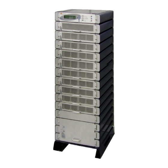
- Page 9 Gamatronic Electronic Industries Ltd. The POWER + is comprised of the following sub-assemblies. System Controller 1-10 UPS modules × 10kVA Static Switch Module System Controller 10kVA UPS modules Static Switch POWER + System - full complement POWER + User Guide, Release 3.4...
-
Page 10: System Controller
Gamatronic Electronic Industries Ltd. System Controller The POWER + system controller has three purposes: • to allow the user to manage and control the UPS as well as monitor the parameters of all sections of the POWER + via the control panel •... -
Page 11: Operating Modes
Gamatronic Electronic Industries Ltd. PERATING ODES The POWER + UPS functions to supply AC electrical power to your load. While using the POWER + , three modes of operation are possible: • Normal operation • Battery operation • Bypass operation Normal Operation The UPS is almost always in normal operation mode. -
Page 12: User Interface
Gamatronic Electronic Industries Ltd. NTERFACE This section describes the buttons and indicators used to operate the POWER + . Control Panel The POWER + Control Panel, located on the front of the controller, provides the user with an interface to the POWER + system. It includes an LCD display, a keypad, buttons and indicators for monitoring and controlling the UPS configuration and functions. -
Page 13: Static Switch Panel
Gamatronic Electronic Industries Ltd. Static Switch Panel The static switch panel, located on the front of static switch module, provides the user with the status of the static switch module. All the functions and indications are available on the POWER + Control Panel. -
Page 14: Navigation And Operation Keypad
Gamatronic Electronic Industries Ltd. L O A D L E V E L G A M A T R O N I C - - - 1 1 : 2 0 : 2 5 - - - _ _ _ _ _... -
Page 15: Status Indicators
Gamatronic Electronic Industries Ltd. Status Indicators The status indicators show precisely what is running and how the UPS is providing power to the load. The diagram below shows the power source and destination routes in use for each of the 3 automated operation modes. - Page 16 Gamatronic Electronic Industries Ltd. Operation Buttons The operation buttons illustrated below are “soft” switches. • On/Off resets the entire UPS • Alarm silence shuts the alarm sounder • Inv/Byp allows the maintenance engineer to manually change the operation mode UPS ON/OFF switch...
-
Page 17: Power + Operation Modes
Gamatronic Electronic Industries Ltd. POWER + Operation Modes Normal Operation L O A D L E V E L G A M A T R O N I C - - - 1 1 : 2 0 : 2 5 - - -... - Page 18 Gamatronic Electronic Industries Ltd. Bypass Operation (Automatic) L O A D L E V E L G A M A T R O N I C - - - 1 1 : 2 0 : 2 5 - - -...
- Page 19 Gamatronic Electronic Industries Ltd. Emergency Power Off - EPO (Manual) An external Emergency Power Off (EPO) switch may be installed by the customer. The EPO switch cuts power to the load in emergency situations. Once switched OFF by the EPO, the POWER + must be restarted manually.
-
Page 20: First -Time Setup
Gamatronic Electronic Industries Ltd. IRST ETUP Installation and Start-Up Sequence Preparation 1. Prepare the proper infrastructure for the POWER + with adequate cables and connections. 2. Prepare the POWER + for installation. Ensure all components and modules are complete and securely fastened to their shelves. -
Page 21: Ac Input/Output Main Terminals
Gamatronic Electronic Industries Ltd. W A I T F O R R E S U L T S . . . Power up S T A T I C R A M : P A S S E D R . T... -
Page 22: Power + Start - Up
Gamatronic Electronic Industries Ltd. POWER + S TART This section describes the start-up procedures for the operator after a POWER + shutdown. L O A D L E V E L G A M A T R O N I C... - Page 23 Gamatronic Electronic Industries Ltd. Connect the load and observe the results on the display. Output Load level bar graph Current L O A D L E V E L G A M A T R O N I C - - - 1 1 : 2 0 : 2 5 - - -...
-
Page 24: Power + Shutdown (Switching To Bypass)
Gamatronic Electronic Industries Ltd. POWER + Shutdown (Switching to Bypass) Switch the load OFF. Press twice on the On/Off button. Wait 2 minutes for the POWER + to shut down. The control screen will indicate UPS OK (OFF). L O A D L E V E L... -
Page 25: Power + Control Panel
Gamatronic Electronic Industries Ltd. POWER + C ONTROL ANEL The POWER + system is equipped with an LCM display (LCD) and touch pad control panel that enables the user to effectively manage the UPS system. Once POWER + is installed, the control panel serves as the user’s primary interface with the system. -
Page 26: Quick-Reference Summary Of Power+ Menu Functions
Gamatronic Electronic Industries Ltd. Quick-Reference Summary of Power+ Menu Functions To access the POWER + main menu, press the “ENT” key. 1 > S Y S T E M 4 > H I S T O R Y 7 > S E T U P... - Page 27 Gamatronic Electronic Industries Ltd. The “SETUP” submenu, option “7” from the main menu: SETUP submenu Option 1: ALARM SET 1> AC VOLT 1) Set AC High & Low Alarm Levels • Set the AC low voltage and AC high voltage alarm levels 2) Set AC Alarms Hysteresis •...
- Page 28 Gamatronic Electronic Industries Ltd. SETUP submenu Option 3: BATTERY 1> TEST-VOLTAGE ● Set the battery test DC voltage (lowest) 2> TEST ALARM Set the low battery DC voltage for alarm ● 3> CURRENT-LIMIT 1) Current Limit Value Setup 1> Set C. Limit Of Battery #1 (Value) •...
- Page 29 Gamatronic Electronic Industries Ltd. 8) ENABLE/DIS OPTIONS 1> ENABLE/DISABLE SHUTDOWN by long AC FAIL (On/Off) • Enable or disable automatic shutdown after 3 hours of power failure 2> ENABLE/DISABLE Current Sensors (On/Off) • Enable or disable the usage of battery current sensors 3>...
- Page 30 Gamatronic Electronic Industries Ltd. 4> Dry4 Association • Set the alarms that will trigger dry contact number 4 5> Dry5 Association • Set the alarms that will trigger dry contact number 5 6> Dry6 Association • Set the alarms that will trigger dry contact number 6 7>...
- Page 31 Gamatronic Electronic Industries Ltd. SETUP submenu Option 9: SILICON 2> RESET LOG ● Reset (clear) the controller’s history log 3> DEFAULTS 1) Restore Factory Defaults… • Restore the controller values to the factory preset and restart the controller – soft reset, reapplies the factory settings 2) Restore User Defaults…...
-
Page 32: Power
Gamatronic Electronic Industries Ltd. OWER UNCTIONS IN ETAIL This chapter describes the functions available through the POWER + Main Menu and its submenus. Main Menu Press the Enter button to display the main menu. Note: To return to the main menu at any time, press the Escape button and then the Enter button. -
Page 33: System
Gamatronic Electronic Industries Ltd. System From the main menu select option 1 (System) to show the DC voltages (positive, negative and summary): B A T T C U R R : - - - - - - - > T O T A L + 0 5 3 . 0 A... - Page 34 Gamatronic Electronic Industries Ltd. P H A S E : - - R - - - - S - - - - T - - System menu I N : 2 3 5 V / 0 4 4 . 0 A 2 3 4 V / 0 4 4 . 0 A 2 3 4 V / 0 4 2 . 0 A O U T : 2 3 1 V / 0 4 3 .
- Page 35 Gamatronic Electronic Industries Ltd. b a t t f u s e : b a d e m e r g e n c y : o p e N System menu o p e n o p e n...
-
Page 36: Ups Module
Gamatronic Electronic Industries Ltd. UPS Module From the main menu, select option 2 (UPS MODULE) and press the Enter button to display the instructions window shown in Figure 21. Press the ▼ key to view information about the UPS modules of the system. -
Page 37: Self-Test
Gamatronic Electronic Industries Ltd. Self-Test From the main menu select option 3 (SELF TEST) to run a self-test of the Main menu POWER + . The self-test displays the window shown in Figure 24. You can run a self-test at any time without interfering in the normal operation of the Option 3 POWER + . - Page 38 Gamatronic Electronic Industries Ltd. Table 2: Log Messages Message Explanation UPSMAJ More than 1 UPS Module is sending an alarm or fault warning UPSMIN Single UPS Module is sending an alarm or fault warning ------ N.A. ------ N.A. LOADBP Load is now running on bypass VIBRA_ Alarm(s) vibrating.
- Page 39 Gamatronic Electronic Industries Ltd. Message Explanation BATFLT Batteries failed last test USER-1 User 1 input open USER-2 User 2 input open USER-3 User 3 input open AC-BRN Input AC supply Brown Out ACIN_H AC input excessive ACFAIL AC input failure...
-
Page 40: Battery
Gamatronic Electronic Industries Ltd. Battery From the main menu select option 5 (Battery) to display the window shown in Figure B A T T E R Y C A P A C I T Y : 0 0 2 0 A H... -
Page 41: Alarm
Gamatronic Electronic Industries Ltd. 1 > B A T T E R Y # 1 : 0 2 0 A H T O T A L C A P . : 0 0 2 0 A H Main menu Option 5... -
Page 42: Setup Menu
Gamatronic Electronic Industries Ltd. Setup Menu From the main menu select option 7 (Setup) to display the window shown in Figure S C - 2 0 1 2 S Y S T E M S E T U P Main... - Page 43 Gamatronic Electronic Industries Ltd. 1 > B A T E N D Alarm set menu 2 > B A T L O W 3 > - - - - - - Option 2 4 > B A T - H I...
- Page 44 Gamatronic Electronic Industries Ltd. Setup menu Option 2 Figure 49: Line configuration menu Module config menu Option 1 Figure 50: Setting number of phases Module config menu Option 2 Figure 51: Setting the sine wave frequency Module config menu Option 3...
- Page 45 Gamatronic Electronic Industries Ltd. Module config menu Option 5 Figure 56: Output fine-tuning – select value Module config menu Option 6 Figure 57: Output fine-tuning – set frequency limits Figure 58: Voltage calibration submenu Figure 59: Enter measured value Setup...
- Page 46 Gamatronic Electronic Industries Ltd. B A T T E R Y ( T E S T ) V O L T A L A R M 3 6 0 . 0 V Battery menu Option 2 Figure 62: Battery test voltage alarm setup 1 >...
- Page 47 Gamatronic Electronic Industries Ltd. A B S O L U T M I N I M U M V O L T A G E W H I L E C M P E N S A T . Floating mode V O L T A G E S E T T I N G : 4 0 0 .
- Page 48 Gamatronic Electronic Industries Ltd. F L O A T I N G C H A R G E S E T U P Equalizing menu V O L T A G E S E T T I N G : 4 3 2 . 0 V Option 2 Figure 76: Setup –...
- Page 49 Gamatronic Electronic Industries Ltd. 1 2 3 4 Service menu + + + + S E T U P S S ( U P = O N < + > , D O W N = O F F < - > )
-
Page 50: Static Sw
Gamatronic Electronic Industries Ltd. S E T I P A D D R E S S NW setup menu 1 9 2 . 1 6 8 . 0 0 0 . 2 5 2 Option 1 Figure 88: Service – setting IP address... -
Page 51: Alarm Dry Contacts
Gamatronic Electronic Industries Ltd. Alarm Dry Contacts 1 > d r y 1 a s s o c i a t i o n 4 > d r y 4 a s s o c i a t i o n... -
Page 52: System Controller Setup Verification
Gamatronic Electronic Industries Ltd. System Controller Setup Verification The process described in this section lets you check the controller settings. This verification procedure is available for software versions beginning from 050106. ACCESS Press ESCAPE key and hold it for 3S. Using ARROW UP/DOWN key, select GENERAL (8) and press ENTER. - Page 53 Gamatronic Electronic Industries Ltd. SCREEN 2 To access SCREEN 2 press the key ARROW RIGHT when SCREEN 1 is selected. a) #OF PHASE: FORCE 3 for 3 phase output, FORCE 1 for single phase output or AUTO when the mode is defined by DIP SWITCH of the modules.
-
Page 54: Snmp Agent
The SNMP agent can provide real-time notification of UPS events in several modalities; for example, via email or SMS. POWER + PSM-AC software, available from Gamatronic, enables you to monitor and control the POWER UPS system. -
Page 55: Wireless
(control center, technician, etc.) detailing the faults. WING can operate through a variety of parallel connections, protocols and applications at the same time. It is compatible with all Gamatronic products, as well as with the products of many other manufacturers. -
Page 56: Wing Configurations
Gamatronic Electronic Industries Ltd. The system replies, informing the sender whether the command was performed. The board can filter the received messages by authorizations (complete management/monitoring only/none). The WING scans the remote power system every three seconds and alerts all the predefined recipients. - Page 57 Gamatronic Electronic Industries Ltd. Figure 97: WING optional configurations POWER + User Guide, Release 3.4...
-
Page 58: Power + Specifications
Gamatronic Electronic Industries Ltd. POWER + S PECIFICATIONS Table 3: Specifications POWER TECHNICAL DATA Topology On line Battery, Double Conversion, VFI Construction Modular parallel hot-plugged modules Operation Continuous Input Voltage (V) 3 × 400+ N Voltage range (%) – 27 and + 20 Current (A) 3 ×... - Page 59 Gamatronic Electronic Industries Ltd. SYSTEM CONTROLLER – TECHNICAL DATA Micro Controller core 16 bit Display 4 × 40 characters LCD with backlight Other indicators 8 LEDs, buzzer Analog input channels 4 input dry contacts (N.C.) Real Time Clock (RTC) Yes, with backup...
- Page 60 Tel-Aviv Sales Office 34 Habarzel Street, Ramat Hachayal, Tel-Aviv Tel: +972-3-6499940 Fax +972-3-6449791 Gamatronic Singapore Sales Office email: singapore@gamatronic.co.il Gamatronic (UK) Ltd. Gamatronic House, Stephenson Court, Priory Business Park, Bedford MK44 3US, United Kingdom Tel: +44 (0)1234 831111 Fax: +44 (0)1234 831114 email: info@gamatronic.net...
Need help?
Do you have a question about the POWER+ and is the answer not in the manual?
Questions and answers