Table of Contents
Advertisement
Quick Links
POWER
M
O
D
U
L
A
R
M
O
D
U
L
A
R
R
M
1
0
0
,
3
2
R
M
1
0
0
,
3
2
M
O
D
E
L
X
M
O
D
E
L
X
U
s
e
U
s
Release 1.3, October 2015
G
AMATRONIC
17 Hartom St., PO Box 45029, Jerusalem 9777517, Israel
Tel: +972-2-588-8222
Email: info@gamatronic.co.il
+
U
P
S
U
P
S
S
Y
S
S
Y
S
0
8
V
,
1
0
V
A
0
8
V
,
1
0
V
A
A
C
K
A
C
K
r
G
u
i
d
e
e
r
G
u
i
d
e
E
I
LECTRONIC
NDUSTRIES
Fax: +972-2-582-8875
Website: www.gamatronic.com
T
E
M
T
E
M
1
0
0
V
A
1
0
0
V
A
T
O
K
T
O
K
L
.
TD
2MUM-PP/28
Advertisement
Table of Contents

Related Manuals for Gamatronic PowerPlus RM 100


Summary of Contents for Gamatronic PowerPlus RM 100
- Page 1 POWER Release 1.3, October 2015 AMATRONIC LECTRONIC NDUSTRIES 17 Hartom St., PO Box 45029, Jerusalem 9777517, Israel Tel: +972-2-588-8222 Fax: +972-2-582-8875 Email: info@gamatronic.co.il Website: www.gamatronic.com 2MUM-PP/28...
- Page 2 Gamatronic is not responsible for any damage to the product due to unauthorized repair work, misuse or abuse of the product, or force majeure. If the product is delivered without batteries, Gamatronic is not responsible for any damage or malfunction due to incorrect wiring of the batteries.
-
Page 3: Table Of Contents
AMATRONIC LECTRONIC NDUSTRIES TABLE OF CONTENTS + RM100 ( ) .............. 1 OVING THE OWER AND ITS BATTERY CABINET ....................2 MPORTANT AFETY NSTRUCTIONS 2.1 Do’s ............................2 2.2 Don’ts ........................... 3 RM100 ................... 5 NTRODUCTION TO THE OWER 3.1 POWER + features: ......................5 3.2 Ac and dc fuses ........................ - Page 4 AMATRONIC LECTRONIC NDUSTRIES 7.6.2 Battery trip coil ...................... 41 7.6.3 Emergency power-off .................... 42 7.7 Dry Contacts ........................43 7.8 Inspections to be performed prior to installation ..............44 7.9 Installation Procedure ......................45 7.10 First-time Startup ........................ 46 7.11 Checks to be performed following initial startup ..............49 7.12 Connection diagram ......................
- Page 5 AMATRONIC LECTRONIC NDUSTRIES 10.10.8 Activating the Battery Test .................. 105 10.10.9 Setting the Automatic Battery Test Period ............105 10.10.10 Setting the Automatic Battery Test Top Time ..........106 10.10.11 Setting the N Battery Capacity ..............107 10.10.12 Activating ‘Auto’ Test ..................108 10.10.13 Enabling/Disabling Options ................
- Page 6 AMATRONIC LECTRONIC NDUSTRIES 11.3.7.7 Defining email notification targets ..................152 11.3.7.8 Defining SMS notifications ....................153 12. U ................... 154 SING THE WITH A GENERATOR 12.1 The Automatic Transfer Switch (ATS) ................154 13. SNMP ..........................156 AGENT 14. W ) ..................
- Page 7 AMATRONIC LECTRONIC NDUSTRIES Figure 26: Preferred generator (neutralized) and connection (3-pole) ..........33 Figure 27: Ground connections on theUPS cabinet roof ..............34 Figure 28: Crimp -type cable shoes recommended for all ground cables ......... 35 Figure 29: Ground studs on UPS cabinet roof, view from below ............35 Figure 30: Ground studs on inside of batt.
- Page 8 AMATRONIC LECTRONIC NDUSTRIES Figure 78: Static switch menu ......................65 Figure 79: Alarm set sub-menu ......................66 Figure 80: Module configuration sub-menu ..................66 Figure 81: Battery menu ........................66 Figure 82: Service sub-menu ......................67 Figure 83: Configure sub-sub-menu ....................68 Figure 84: Silicon sub-menu .......................
- Page 9 AMATRONIC LECTRONIC NDUSTRIES Figure 130: Set BATEND ........................88 Figure 131: Battery floating charge alarm setup menu ..............88 Figure 132: Set BATLOW ........................88 Figure 133: Battery floating charge alarm setup menu ..............88 Figure 134: Set BAT-HI ........................88 Figure 135: Alarm set menu .......................
- Page 10 AMATRONIC LECTRONIC NDUSTRIES Figure 182: Enable/Disable temperature compensation ..............103 Figure 183: Select Set ABSOLUTE Max & Min Voltages ..............103 Figure 184: Select Set absolute minimum output voltage ..............104 Figure 185: Set absolute minimum output voltage when compensating ......... 104 Figure 186: Select Set absolute maximum output voltage ...............
- Page 11 AMATRONIC LECTRONIC NDUSTRIES Figure 234: Service > Configure menu .................... 120 Figure 235: Dry relay menu ......................120 Figure 236: Set dry contact N alarm associations ................120 Figure 237: Enable / disable alarms ....................120 Figure 238: Service > Configure menu .................... 121 Figure 239: DC-I menu ........................
- Page 12 AMATRONIC LECTRONIC NDUSTRIES Figure 286: Select General ......................134 Figure 287: General (Screen 1) ....................... 134 Figure 288: General (Screen 2) ....................... 135 Figure 289: General (Screen 3) ....................... 136 Figure 290: General (Screen 4) ....................... 136 Figure 291: Power+ controller rear panel ..................137 Figure 292: Main Screen of the Power+ Web interface ..............
- Page 13 AMATRONIC LECTRONIC NDUSTRIES Table 17: Commands available on the “Control” screen ..............144 Table 18: Defining computers for auto-shutdown ................150 Table 19: Fields in the email notifications screen ................152 Table 20: Fields in the SMS notification target definition screen ............. 153 Table 21: List of SMS commands ....................
- Page 14 AMATRONIC LECTRONIC NDUSTRIES IN THE EVENT THAT SYSTEM OUTPUT CAPACITY IS INCREASED ABOVE THE ORIGINAL FACTORY CONFIGURATION, THE SYSTEM NAMEPLATE MUST BE UPDATED TO INDICATE THE NEW POWER AND CURRENT CAPACITY. This condition applies when new, non-redundant power modules are added to the system or when formerly redundant modules are designated as non-redundant.
-
Page 15: And Its Battery Cabinet )
Gamatronic Electronic Industries Ltd. + RM100 ( OVING THE OWER AND ITS BATTERY CABINET The Power+RM100 is usually shipped in its cabinet. After unpacking the RM100, you will notice two metal flanges at the base of the cabinet – one on the left side and one on the right side of the cabinet. These flanges can be used to secure the RM100 to the ground if desired. -
Page 16: Important Safety Instructions
Gamatronic Electronic Industries Ltd. MPORTANT AFETY NSTRUCTIONS (SAVE THESE INSTRUCTIONS) This manual contains important instructions for the Power+ RM100 3x208 Vac model. The PowerPlus UPS system is designed for industrial applications and harsh environments. Nevertheless the PowerPlus system should be handled with appropriate care, according to the following guidelines. -
Page 17: Don'ts
Gamatronic Electronic Industries Ltd. Don’ts • Do not open the cover of the UPS or the battery cabinets under any circumstances. All UPS panels and doors should be closed. • Do not insert any objects through the ventilation holes. •... - Page 18 Gamatronic Electronic Industries Ltd. WARNING: RISK OF SEVERE DAMAGE TO THE UPS!!! his system uses the neutral line for operation. Therefore, it is strictly forbidden to connect this system to the ac power source without a neutral (null) conductor!! Failure to use a neutral conductor may cause permanent damage to the system.
-
Page 19: Introduction To The Power Plus Rm100
Gamatronic Electronic Industries Ltd. RM100 NTRODUCTION TO THE OWER In general, an Uninterruptible Power Supply (UPS) provides backup power for use when the utility ac electric power mains fail or drop to an unacceptable voltage level. POWER + is a whole lot more. -
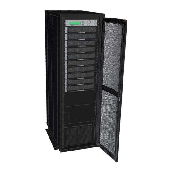
Page 20: Figure 3: Main Subassemblies Of The Rm100
Gamatronic Electronic Industries Ltd. ESCRIPTION 19-inch cabinet System controller module From 1 to 10 UPS power modules, 10 kVA each Static switch assembly Figure 3: Main subassemblies of the RM100 POWER + RM100, 3 208 V, User Guide, 1.3... -
Page 21: Ac And Dc Fuses
Gamatronic Electronic Industries Ltd. Ac and dc fuses Ac and dc fuses are located on the rear panel of the UPS, above the terminals. See Figure 21 on page 26. Ac input/output main terminals The main input and output terminals are located at the lower rear of the unit. The terminals are used to connect the ac input and bypass inputs, the battery, and the ac output. -
Page 22: Battery
Gamatronic Electronic Industries Ltd. ATTERY The POWER+ battery bank is used as a backup in the event that the utility ac input fails. The batteries are housed in an external cabinet (cat. no. 29B020128-PPE) next to the POWER+ cabinet. The batteries are charged by the rectifier that supplies both the inverter and the battery charger. Batteries should always be located next to the UPS. - Page 23 Gamatronic Electronic Industries Ltd. ATTENTION - RISQUE DE DÉCHARGE ÉLECTRIQUE ! Ne pas ouvrir le boîtier de la batterie, gardez l'armoire verrouillée. L'entretien des batteries doit être effectué ou supervisé par un personnel qualifié de batteries et les précautions nécessaires. Garder le personnel non autorisé loin des batteries.
-
Page 24: Connecting The Battery Cabinet To The Ups
If the UPS is delivered without batteries, Gamatronic is not responsible for any damage or malfunction due to incorrect wiring of the batteries. -
Page 25: Figure 4: Battery Cabinet
Gamatronic Electronic Industries Ltd. ESCRIPTION Cover for terminal connections Battery cabinet terminals, uncovered. Note: When connecting the external battery cabinet to the UPS, connect the terminals according to the numbers. That is, connect battery cabinet terminal 1 (above) to battery terminal 1 on the UPS, 2 to 2, 3 to 3, and 4 to 4. -
Page 26: Figure 5: One Battery Box
Gamatronic Electronic Industries Ltd. • The battery cabinet (cat. no. 29B020128-PPE) contains two battery boxes. • Each battery box contains eight drawers of batteries. • Each drawer contains eight batteries. Figure 5: One battery box Figure 6: One battery drawer POWER + RM100, 3 208 V, User Guide, 1.3... -
Page 27: Figure 7: Battery Cabinet Wiring
Gamatronic Electronic Industries Ltd. Figure 7: Battery cabinet wiring POWER + RM100, 3 208 V, User Guide, 1.3... -
Page 28: Battery Replacement Instructions
Gamatronic Electronic Industries Ltd. Battery replacement instructions To replace the batteries in the battery cabinet (cat. no. 29B020128-PPE): Turn off load devices (recommended). Disconnect the ac input to the UPS (recommended). On the rear of the battery cabinet, switch OFF the battery cabinet circuit breaker (see Figure 4). -
Page 29: Operating Modes
Gamatronic Electronic Industries Ltd. PERATING MODES The POWER + UPS functions to supply ac electrical power to your load. While using the POWER + , three modes of operation are possible: • Normal operation • Battery operation • Bypass operation All three operation modes are encountered during normal UPS use to constantly provide regulated voltage to the load. -
Page 30: Maintenance Bypass Mode
Gamatronic Electronic Industries Ltd. Maintenance bypass mode In maintenance bypass mode, the UPS output terminals continue to supply power to the load, but the interior of the UPS is disconnected from the main power flow. This enables a maintenance technician to work safely on the UPS without any interruption of power to the load. -
Page 31: User Interface
Gamatronic Electronic Industries Ltd. 6. U SER INTERFACE This section describes the buttons and indicators used to operate the POWER + . Control Panel The POWER + Control Panel, located on the front of the controller, provides the user with an interface to the POWER + system. -
Page 32: Static Switch Panel
Gamatronic Electronic Industries Ltd. Static Switch Panel The static switch panel, located on the front of static switch module, provides the user with the status of the static switch module. All the functions and indications are available on the POWER + Control Panel. -
Page 33: Power + Control Screen
Gamatronic Electronic Industries Ltd. POWER + control screen The POWER + control screen is illustrated below. It is part of the control panel described on page 17. How to read and understand the POWER + control screen is described in detail in Chapter 9, POWER +... -
Page 34: Navigation And Operation Keypad
Gamatronic Electronic Industries Ltd. Navigation and Operation Keypad The navigation and operation keypad works in conjunction with the control screen. It allows you to navigate through the available menus using the direction arrow buttons and the Enter and Escape buttons to select or quit, respectively. -
Page 35: Status Indicators
Gamatronic Electronic Industries Ltd. Status Indicators The status indicators show precisely what is running and how the UPS is providing power to the load. The diagram below shows the power source and destination routes in use for each of the 3 automated operation modes. -
Page 36: Operation Buttons
Gamatronic Electronic Industries Ltd. Operation Buttons The operation buttons illustrated below are “soft” switches. • On/Off resets the entire UPS • Alarm silence shuts the alarm sounder • Inv/Byp allows the maintenance engineer to manually change the operation mode Table 2: Operation buttons... -
Page 37: Power + Operation Modes
Gamatronic Electronic Industries Ltd. POWER + Operation Modes 6.9.1 Normal Operation During normal operation, the UPS draws power from the ac line, feeds dc to the inverter, which provides ac to the load. LOAD LEVEL ---11:20:25--- _____ 030A, 120V BATTERY:... -
Page 38: Bypass Operation (Automatic)
Gamatronic Electronic Industries Ltd. Figure 18: AC power failure indication 6.9.3 Bypass Operation (Automatic) During Bypass operation, the ac feeds the load via the bypass static switch. The red alarm flashes to indicate abnormal status. LOAD LEVEL ---12:01:11--- _____ 030A, 120V... -
Page 39: System Installation
Gamatronic Electronic Industries Ltd. YSTEM INSTALLATION WARNING! This UPS is intended for installation in a temperature-controlled, indoor area that is free from conductive contaminants. ATTENTION! Cet onduleur est conçu pour une installation dans une température contrôlée, espace intérieur qui est exempt de contaminants conducteurs. -
Page 40: Figure 21: Rm100 3X208 V, Rear View
Gamatronic Electronic Industries Ltd. ESCRIPTION Ac input terminals. From top to bottom: Rectifier ac input L1 Bypass ac input L1 Rectifier ac input L2 Bypass ac input L2 Rectifier ac input L3 Bypass ac input L3 Neutral Ac output terminals. -
Page 41: Figure 22: Cable Entry From The Top Or Bottom Of Ups Cabinet
Gamatronic Electronic Industries Ltd. Figure 22: Cable entry from the top or bottom of UPS cabinet Figure 23 (3-3 configuration) below illustrates the cabling of the POWER+ system to the mains electricity cabinet. POWER + RM100, 3 208 V, User Guide, 1.3... -
Page 42: Figure 23: Connection Diagram For 3-3 Configuration
Figure 23: Connection diagram for 3-3 configuration Note: If you intend to install the PowerPlus in a 2-2 configuration it is important that you first consult with Gamatronic’s engineering department. The power output in the 2-2 configuration is limited to 50 kVA. -
Page 43: The Power+ Always Requires A Neutral Line
Gamatronic Electronic Industries Ltd. The Power+ always requires a neutral line During both installation and operation of the Power +, a neutral line must always be connected to the UPS. This neutral line shall be connected during the entire period that the UPS is working, and shall not be... - Page 44 Gamatronic Electronic Industries Ltd. POWER + RM100, 3 208 V, User Guide, 1.3...
-
Page 45: Figure 24: Wrong Way To Connect Ups With Four-Pole Switch
Gamatronic Electronic Industries Ltd. Figure 24: Wrong way to connect UPS with four-pole switch WARNING! A 4-pole switch may disconnect the neutral line if improperly connected! POWER + RM100, 3 208 V, User Guide, 1.3... -
Page 46: Figure 25: Acceptable Connection For Grounded Generator And 4-Pole Switch
Gamatronic Electronic Industries Ltd. Figure 25: Acceptable connection for grounded generator and 4-pole switch POWER + RM100, 3 208 V, User Guide, 1.3... -
Page 47: Figure 26: Preferred Generator (Neutralized) And Connection (3-Pole)
Gamatronic Electronic Industries Ltd. Figure 26: Preferred generator (neutralized) and connection (3-pole) POWER + RM100, 3 208 V, User Guide, 1.3... -
Page 48: Ground Connections
Gamatronic Electronic Industries Ltd. Ground connections There are three ground connections that must be made: • Between a ground stud on UPS cabinet and the building ground. • Between a ground stud on UPS cabinet and the electrical board ground line (or the ground connection on the load device). -
Page 49: Figure 28: Crimp -Type Cable Shoes Recommended For All Ground Cables
Gamatronic Electronic Industries Ltd. Figure 29 through Figure 31 below, and Table 4 and Table 5, detail the ground connections for the UPS and battery cabinet. It is recommended that all ground cables discussed here be finished with crimp lug type cable shoes. -
Page 50: Figure 30: Ground Studs On Inside Of Batt. Cabinet Roof
Gamatronic Electronic Industries Ltd. Figure 30: Ground studs on inside of batt. cabinet roof Figure 31: Ground bus bar at base of UPS rear Table 5: Key to Figure 30 and Figure 31 above ROUND NAME NSTRUCTIONS Connect a cable to either of the ground studs (10 mm diam.) in the roof of... -
Page 51: Over-Current Protection
Gamatronic Electronic Industries Ltd. Over-Current Protection CAUTION! To reduce the risk of fire, connect the UPS only to a circuit provided with maximum branch circuit over-current protection as indicated in Table 6, in accordance with the National Electric Code, NSI/NFPA 70. -
Page 52: Dc Wiring
Gamatronic Electronic Industries Ltd. Ac input 50 kVA Ac input bypass 175 A Load Ac input 60 kVA Ac input bypass 225 A Load Ac input 70 kVA Ac input bypass 250 A 500 kcmils, Load 600 V, 75 °C copper wire... -
Page 53: Fuses
Gamatronic Electronic Industries Ltd. Fuses WARNING! To reduce the risk of fire, replacement fuses must be of the same type and rating as the original. AVERTISSEMENT ! Pour réduire le risque du feu, les fusibles de rechange doivent être du mêmes type et estimation que l'original. -
Page 54: Dc Distribution Fuses
Gamatronic Electronic Industries Ltd. DC DISTRIBUTION FUSES Verify that the appropriate dc fuses are present. All dc fuses are located on the opposite side (the front side) of the dc distribution panel. There are two fuses for each power module and for the controller – one for the positive line and one for the negative line. -
Page 55: Special Terminal Connections
Gamatronic Electronic Industries Ltd. Special terminal connections This section describes the special-purpose terminal connections of the POWER+. The special-purpose terminal connections on the 100 kVA model are on the rear side of the UPS near the power terminals and can be seen in Figure 21 on page 26. Figure 34 shows the connections to external devices. -
Page 56: Emergency Power-Off
Gamatronic Electronic Industries Ltd. 7.6.3 Emergency power-off An external Emergency Power-Off (EPO) switch can be installed by the customer to enable immediate shutdown of the UPS. Once switched off by the EPO, the POWER+ must be restarted manually. The UPS has two terminals marked "EPO" for connection of an EPO switch (Figure 34). Use of a large mushroom-type N.O. -
Page 57: Dry Contacts
Gamatronic Electronic Industries Ltd. Dry Contacts On the uppermost green plug of the Controller module, on the right side of the plug, there are four alarm contacts. We describe them here, in right-to-left order. Figure 35: Dry contacts on rear of controller The first contact on the right is COM. -
Page 58: Inspections To Be Performed Prior To Installation
Circuit breakers on the electrical Must be in accordance with Gamatronic system board supplying the system specifications and connection schematic. Diameter of input and output power... -
Page 59: Installation Procedure
(see step 2 above). Connect neutral and ground lines to busses as per the connection diagram. If the UPS is delivered without batteries, Gamatronic is not responsible for any damage or malfunction due to incorrect wiring of the batteries. -
Page 60: First-Time Startup
Gamatronic Electronic Industries Ltd. 7.10 First-time Startup This section describes the procedure for starting up the Power+ for the first time, after having completed the installation process described in the previous chapter. Ensure that the maintenance bypass switch is set to NORMAL (OFF), and that no load devices are connected to the UPS. -
Page 61: Figure 39: Start-Up Screen 4
Gamatronic Electronic Industries Ltd. Figure 39: Start-up screen 4 During this step, the LEDs are also checked sequentially. Finally, the normal default screen is displayed. Verify that the correct number of phases is displayed: For 3-3 configuration, under the LOAD LEVEL heading, you should see a line for L1, L2, and L3 as in Figure 40. - Page 62 Gamatronic Electronic Industries Ltd. IMPORTANT NOTE: YOUR POWER SYSTEM HAS BEEN DELIVERED TO YOU WITH THE OUTPUT VOLTAGE AND FREQUENCY SET TO MATCH YOUR REQUIREMENTS CHECK NOW TO VERIFY THAT THESE SETTINGS ARE CORRECT 10.9.2 TO SET MODULE S FREQUENCY...
-
Page 63: Checks To Be Performed Following Initial Startup
User Guide and that no alarms or fault indications are evident NOTE: It is the responsibility of the customer to notify Gamatronic Electronic Industries Ltd. and receive approval for any deviations from these requirements. O COMP LETE THE INS TALLATION CHECKLIS T... -
Page 64: Connection Diagram
Gamatronic Electronic Industries Ltd. 7.12 Connection diagram Figure 44: Connection diagram (for completion by the customer) POWER + RM100, 3 208 V, User Guide, 1.3... -
Page 65: 7.13 Configuration
Gamatronic Electronic Industries Ltd. 7.13 Configuration Perform the following configuration steps from the Control Panel. 7.13.1 Check Configured Modules Verify that the number of configured modules matches the desired output power, and verify that the number of redundant modules is correct. Modify as needed. -
Page 66: Figure 48: Service Menu
Gamatronic Electronic Industries Ltd. Select Configure, option 5, to configure the Power+ modules: [Main Menu > SETUP > (password) > Ent > Service] 1> ------ 4> DryOut Test 7> -------- 2> UPSs 5> Configure 8> Powr.Calib 3> ------- 6> En/Dis shar 9> SC2012.. -
Page 67: Check Total Ampere-Hours
Gamatronic Electronic Industries Ltd. 7.13.2 Check Total Ampere-Hours This procedure is designed to ensure that the total capacity of the batteries attached to Power+ matches the definition of the total capacity in the System Controller. Check the total capacity of the installed batteries attached to Power+. -
Page 68: Set Date And Time And Serial Number
Gamatronic Electronic Industries Ltd. 7.13.3 Set Date and Time and Serial Number To verify the date and time set in the System Controller and make sure that they are correct: Use the keys to select the year, month, day, hour, minute, or second you wish to modify, then use the keys to set the correct value for the selected item. -
Page 69: Figure 58: Ip Address
Gamatronic Electronic Industries Ltd. Use the arrow keys to set the IP address, and then press Ent: [Main Menu > SETUP > (password) > Ent > Service > SC2012 > Network > Set IP ADDRESS] Set IP ADDRESS 157.211.000.252 Figure 58: IP Address Use the arrows keys to set the gateway and press Ent: [Main Menu >... -
Page 70: 7.14 Testing
Gamatronic Electronic Industries Ltd. 7.14 Testing Perform the following tests on the Power+ unit. 7.14.1 Blackout Test This test is designed to verify the operation of Power+ in the event of a blackout, when no ac power is supplied to the UPS. -
Page 71: Check Ip Communication With Controller
Gamatronic Electronic Industries Ltd. 7.14.4 Check IP Communication with Controller This test is designed to verify that the System Controller is properly configured for communication and that the Web server built into the System Controller is functioning properly. If you do not intend to use remote monitoring of the UPS at this time you can skip this test. -
Page 72: Test Wing Option
Gamatronic Electronic Industries Ltd. 7.14.5 Test Wing Option If Wing has been installed in the UPS, this test is designed to check that it is working properly by sending an SMS message through the Web interface of Wing to a specified phone number. -
Page 73: Power + Routine Start Up
Gamatronic Electronic Industries Ltd. POWER + ROUTINE START Start-up after Shutdown This section describes the start-up procedures for the operator after a POWER + shutdown. After shutdown, the UPS on, Alarm and Load indicators will flash. After a normal POWER+ shutdown the display screen indicates a load of zero amps, the UPS status is “OK, OFF”;... -
Page 74: Figure 67: Normal Operation Indication
Gamatronic Electronic Industries Ltd. If the inverter indicator on the Static Switch panel is OFF: ● Press the Inv/Byp button on the static switch panel to switch the inverter ON and wait for the indicator to light. ● Press the Inv/Byp button on the lower right of the control panel. -
Page 75: Power + Shutdown (Switching To Bypass)
Gamatronic Electronic Industries Ltd. POWER + Shutdown (Switching to Bypass) Switch the load OFF. Press twice on the On/Off button. Wait 2 minutes for the POWER + to shut down. The control screen will indicate UPS OK (OFF). LOAD LEVEL... -
Page 76: Power + Total Shutdown (No Ac Output)
Gamatronic Electronic Industries Ltd. POWER + Total Shutdown (No Ac Output) Switch the load OFF. Press and hold the On/Off button for 10 seconds. The control screen will indicate UPS OK (OFF). LOAD LEVEL ---23:14:40--- L1:__________ 000A, 120V BATTERY: 432V... -
Page 77: Power + Control Panel
Gamatronic Electronic Industries Ltd. POWER + C ONTROL ANEL The POWER+ system is equipped with an LCM (Liquid Crystal Monitor) and touch pad control panel that enables the user to effectively manage the UPS system. Once POWER+ is installed, the control panel serves as the user’s primary interface with the system. -
Page 78: Quick-Reference Summary Of Power+ Menu Functions
Gamatronic Electronic Industries Ltd. Quick-reference summary of Power+ menu functions The following flowcharts detail the structure of the PowerPlus menus. The symbol directs you to a following chart. For example, means "go to the diagram labeled M.7.3. Diagram M.7.3 illustrates sub-option 3 of Main Menu option 7. -
Page 79: Figure 75: System Menu
Gamatronic Electronic Industries Ltd. Figure 75: System menu Figure 76: Battery menu Figure 77: Setup menu Main Menu option 8. (Main Menu) Displays: STATIC SW. • Inverter voltage. • Bypass voltage. • Output current. • Static switch status bytes. Figure 78: Static switch menu POWER + RM100, 3 208 V, User Guide, 1.3... -
Page 80: Figure 79: Alarm Set Sub-Menu
Gamatronic Electronic Industries Ltd. Options 1 on the Setup menu. (Setup Menu) Set: ALARM M.7.1 1. Ac high & low alarm thresholds, Ac alarm hysteresis. 2. Batt. end, batt. low, batt. hi voltages. 7. Over temp., under temp. 9. Integration factor. -
Page 81: Figure 82: Service Sub-Menu
Gamatronic Electronic Industries Ltd. Figure 82: Service sub-menu POWER + RM100, 3 208 V, User Guide, 1.3... -
Page 82: Figure 83: Configure Sub-Sub-Menu
Gamatronic Electronic Industries Ltd. Figure 83: Configure sub-sub-menu Figure 84: Silicon sub-menu POWER + RM100, 3 208 V, User Guide, 1.3... -
Page 83: Ower Menu Functions In Detail
Gamatronic Electronic Industries Ltd. 10. P OWER MENU FUNCTIONS IN DETAIL This chapter describes the functions available through the POWER + Main Menu and its submenus. Note: If you are viewing this file in PDF format, it is possible to search for text in the displayed screens. This eases finding the desired screen. -
Page 84: 10.2 "System" Option
Gamatronic Electronic Industries Ltd. 10.2 “System” Option Figure 86: Main menu option 1 ("System") The SYSTEM option (option 1) shows the dc voltages and current (positive, negative and summary): [Main Menu > SYSTEM] BATT CURR: -----> TOTAL +053.0A BATT POS.: 216V BATT +053.2A (0531) -
Page 85: Figure 88: Output Power Factor 1
Gamatronic Electronic Industries Ltd. View the current output power factors [Main Menu > SYSTEM > ►] OUTPUT TOTAL 000.4 000.2 000.2 000.8 000.0 000.0 000.0 000.0 P.F. 0.00 0.00 0.00 0.00 Figure 88: Output power factor 1 View the current input power factor: [Main Menu >... -
Page 86: Figure 92: Jumper Settings Without Remote Panel
Gamatronic Electronic Industries Ltd. View the system jumper settings without remote panel: [Main Menu > SYSTEM > ▼ ▼ ▼] JMP: JMP1, JMP2, JMP3, JMP6 and JMP9 1. NOT HARD SILICON 2. SILICON MODE 6. NO RMT PAN. 12369 3. CAPACITY LOW 9. -
Page 87: Figure 96: Fuse Status
Gamatronic Electronic Industries Ltd. 10. View status of the fuses: [Main Menu > SYSTEM > ▼ ▼ ▼ ▼ ▼ ▼] BATT FUSE: EMERGENCY: OPEN USER-1: OPEN USER-4: OPEN USER-2: OPEN OPEN USER-3: OPEN OPEN Figure 96: Fuse status 11. View communication with the converter in the transmit mode (for Technicians): [Main Menu >... -
Page 88: 10.3 "Ups Module" Option
Gamatronic Electronic Industries Ltd. 10.3 “UPS module” Option To view voltage and current measurements and other information for each UPS module: Use the ▼ and ▲ keys to scroll between UPS modules. The display shows the voltage and current measurements for each module (see Figure 101 on page 75. -
Page 89: Figure 101: Module Phase Voltages/Currents
Gamatronic Electronic Industries Ltd. View the input and output voltage and current for each phase of a particular UPS module. Scroll down ▼ to view other UPS modules. [Main Menu > UPS MODULE > ▼] PHASE: -L1-- -L2-- -L3— 000V/000.0A 000V/000.0A 000V/000.0A OUT: 000V/000.0A 000V/000.0A 000V/000.0A... -
Page 90: 10.4 "Self-Test" Option
Gamatronic Electronic Industries Ltd. 10.4 “Self-test” Option You can run a self-test at any time without interfering in the normal operation of the POWER + . A self-test is also initiated by the POWER + itself each day at midnight. -
Page 91: 10.5 "History" (Logs) Option
Gamatronic Electronic Industries Ltd. 10.5 “History” (logs) Option The last 255 events reserved in the LOG are displayed, as shown in Figure 106. Figure 105: Main Menu option 4 (“History”) Navigate the LOG by scrolling using the ▲ and ▼ keys. -
Page 92: Figure 107: History Log Scroll
Gamatronic Electronic Industries Ltd. View more details by pressing the ► key. [Main Menu > HISTORY > ►] TIME DATE 1 2 3 4 5 6 7 8 14:36:16 28.02.10 14:37:01 28.02.10 12:27:26 27.02.10 Figure 107: History log scroll Table 11 lists the log messages that can appear on the controller panel. -
Page 93: Table 11: Log Messages
Gamatronic Electronic Industries Ltd. Table 11: Log Messages Message Explanation UPSMAJ More than 1 UPS Module is sending an alarm or fault warning UPSMIN Single UPS Module is sending an alarm or fault warning ------ N.A. ------ N.A. LOADBP Load is now running on bypass. See Table 12 on page 80 to interpret the LOADBP value. -
Page 94: Table 12: Interpreting The Static Switch Transfer Code (Loadbp)
Gamatronic Electronic Industries Ltd. Message Explanation OVLOAD Load current is high UPS-CM One or more UPS’s not responding STRTUP Startup time-stamp ------ N.A. Each message is formatted as follows: Time – HH:MM:SS Date – YY:MM:DD Data – DC voltage between + and – terminals for all events except LOADBP and STSW status for LOADBP events. -
Page 95: 10.6 "Battery" Option
Gamatronic Electronic Industries Ltd. 10.6 “Battery” Option The battery option on the main menu displays information about battery capacity, battery voltage and current, and battery test. Figure 108: Main Menu option 5 (“Battery”) View the battery capacity, charge mode, equalizing running time, and charge current: [Main Menu >... -
Page 96: Figure 110: Battery Equalizing
Gamatronic Electronic Industries Ltd. View next automatic equalizing, remaining equalizing time, total rectifier current, and battery (charging) current: [Main Menu > BATTERY > ▼] Next automatic equalizing: 02 days Remaining equalizing time: ___ minutes Rectifiers total current : 0050A Battery current : 053.0A... -
Page 97: 10.7 "Alarm" Option
Gamatronic Electronic Industries Ltd. View battery capacity: [Main Menu > BATTERY > ▼> ▼> ▼> ▼> ▼] 1> Battery#1: 020 Ah Total Cap.: 0020 Ah Figure 114: Battery capacity Note: Figure 112, Figure 113, and Figure 114 show the individual batteries on the left and the overall total on the right. -
Page 98: Figure 116: Main Menu Option 6 ("Alarm")
Gamatronic Electronic Industries Ltd. Figure 116: Main Menu option 6 (“Alarm”) View alarms 01-12: A + or – before an alarm name indicates the alarm is enabled or disabled, respectively. An asterisk (*) after an alarm name indicates that the alarm is active. -
Page 99: 10.8 "Setup - Alarm Set" Option
Gamatronic Electronic Industries Ltd. 10.8 “Setup – Alarm Set” Option 1) Set AC High & AC alarm setup ◄►▲▼ Low Alarm Levels 1) AC VOLT 2) Set AC Alarms Set AC volt alarms hysteresis ◄►▲▼ Hysteresis Floating charge alarm setup: 1) BATEND voltage setting◄►▲▼... -
Page 100: Setting Ac Voltage Alarms
Gamatronic Electronic Industries Ltd. Select Alarm set: [Main Menu > SETUP > (password) > Ent] 1> Alarm Set 5> Time 9> Silicon 2> Module Conf. 6> Site 3> Battery 7> Password #1 4> Charge 8> Service Figure 122: Setup menu 10.8.1... -
Page 101: Setting Battery Floating Voltage Alarm
Gamatronic Electronic Industries Ltd. Select Set AC Alarms Hysteresis: [Main Menu > SETUP > Ent > (password) > Ent > ALARM SET > AC VOLT] 1> SET AC HIGH & LOW ALARM LEVELS 2> SET AC ALARMS HYSTERESIS PLEASE SELECT... -
Page 102: Figure 130: Set Batend
Gamatronic Electronic Industries Ltd. Use the arrow keys to set BATEND and press Ent: [Main Menu > SETUP > (password) > ALARM SET > FLOAT VOLT > BATEND] FLOATING CHARGE SETUP VOLTAGE SETTING: 170.0V Figure 130: Set BATEND Select BATLOW: [Main Menu >... -
Page 103: Setting Battery Over/Under Temperature Alarms
Gamatronic Electronic Industries Ltd. 10.8.3 Setting Battery Over/Under Temperature Alarms Select TEMPERATURE: [Main Menu > SETUP > (password) > ALARM SET] 1> AC VOLT 5> --------- 9>INTEGRAT. 2> FLOAT VOLT 6> --------- 3> --------- 7> TEMPERATURE 4> --------- 8> ---------... -
Page 104: Setting Battery Integration Alarm
Gamatronic Electronic Industries Ltd. Use the arrow keys to set the battery minimum temperature alarm value, press Ent, and then Esc: [Main Menu > SETUP > (password) > ALARM SET > Temperature > UNDER TEMPERATURE] SET OVER TEMPERATURE ALARM VALUE ( 2 –... -
Page 105: 10.9 "Setup - Module Conf." Option
Gamatronic Electronic Industries Ltd. 10.9 “Setup – Module Conf.” Option 1) Num of phase SET MODULE/S 2) Module/s frequency FREQUENCY Set Module/s 3) Module/s voltage voltage Update Vo/Fr/ph 4) Update Vo/Fr/ph settings Select A Phase Select A Module Select A Value To... -
Page 106: Setting Number Of Phases
Gamatronic Electronic Industries Ltd. Select Module conf.: [Main Menu > SETUP > (password) > Ent] 1> Alarm set 5> Time 9> Silicon 2> Module conf. 6> Site 3> Battery 7> Password #1 4> Charge 8> Service Figure 144: Setup menu 10.9.1... -
Page 107: Setting Module/S Voltage
Gamatronic Electronic Industries Ltd. 10.9.3 Setting Module/s Voltage Select Module/s voltage: [Main Menu > SETUP > (password) > Module conf.] 1. Num of phase 5.Output Adjust 2. Module/s frequency 6.Frequency Limits 3. Module/s voltage 7.DC Calibration 4. Update Vo/Fr/ph 8.AC Calibration Figure 148: Module Config. -
Page 108: Output Adjustment
Gamatronic Electronic Industries Ltd. 10.9.5 Output Adjustment Select Output Adjust: [Main Menu > SETUP > (password) > Module conf.] 1. Num of phase 5.Output Adjust 2. Module/s frequency 6.Frequency Limits 3. Module/s voltage 7.DC Calibration 4. Update Vo/Fr/ph 8.AC Calibration Figure 152: Module Config. -
Page 109: Setting Frequency Limits
Gamatronic Electronic Industries Ltd. 10.9.6 Setting Frequency Limits Select Frequency Limits: [Main Menu > SETUP > (password) > Module conf.] 1. Num of phase 5.Output Adjust 2. Module/s frequency 6.Frequency Limits 3. Module/s voltage 7.DC Calibration 4. Update Vo/Fr/ph 8.AC Calibration Figure 156: Module Config. -
Page 110: Calibrating Ac Voltage
Gamatronic Electronic Industries Ltd. Adjust the measured value using the arrow keys, and press Ent to update: [Main Menu > SETUP > (password) > Module conf. > DC Calibration > Ent] MODULE V. CALIB – 15 Sec to expire #######... -
Page 111: 10.10 "Setup - Battery" Option
Gamatronic Electronic Industries Ltd. 10.10 “Setup – Battery” Option Set battery test 1) Test-Voltage voltage ▲▼◄► Set battery test voltage 2) Test Alarm alarm ▲▼◄► 1) Current Limit Battery current Set charge current limit ▲▼◄► Value Setup limits 3) Current-Limit.. -
Page 112: Setting Battery Test Voltage
Gamatronic Electronic Industries Ltd. To enter Setup, use the default password <<<<<<<< (left arrow key eight times). [Main Menu > SETUP] POWER+ System Setup Type in Level-1 PASSWORD, THEN – ENTER Your privilege will expire after 15 min. PASSWORD:________ Figure 165: Level 1 password access Select Battery: [Main Menu >... -
Page 113: Setting Battery Test Voltage Alarm
Gamatronic Electronic Industries Ltd. 10.10.2 Setting Battery Test Voltage Alarm Select Test Alarm: [Main Menu > SETUP > (password) > Battery] 1> Test-Voltage 5> Battery test… 2> Test Alarm 6> Capacity 0020 AH) 3> Current-Limit.. 7> ‘AuTo’ Test 4> Temp Compensat. 8> Enable/Dis Options... -
Page 114: Setting Battery Current Limit
Gamatronic Electronic Industries Ltd. 10.10.3 Setting Battery Current Limit Select Current-Limit..: [Main Menu > SETUP > (password) > Battery] 1> Test-Voltage 5> Battery test… 2> Test Alarm 6> Capacity 0020 AH) 3> Current-Limit.. 7> ‘AuTo’ Test 4> Temp Compensat. 8> Enable/Dis Options... -
Page 115: Enable/Disable Battery Current Limit
Gamatronic Electronic Industries Ltd. 10.10.4 Enable/Disable Battery Current Limit Select Current-Limit..: [Main Menu > SETUP > (password) > Battery] 1> Test-Voltage 5> Battery test… 2> Test Alarm 6> Capacity 0020 AH) 3> Current-Limit.. 7> ‘AuTo’ Test 4> Temp Compensat. 8> Enable/Dis Options... -
Page 116: Setting Temperature Compensation
Gamatronic Electronic Industries Ltd. 10.10.5 Setting Temperature Compensation Select Temp Compensat.: [Main Menu > SETUP > (password) > Battery] 1> Test-Voltage 5> Battery test… 2> Test Alarm 6> Capacity 0020 AH) 3> Current-Limit.. 7> ‘AuTo’ Test 4> Temp Compensat. 8> Enable/Dis Options... -
Page 117: Setting Disable Temperature Compensation
Gamatronic Electronic Industries Ltd. 10.10.6 Setting Disable Temperature Compensation Select Temp Compensat.: [Main Menu > SETUP > (password) > Battery] 1> Test-Voltage 5> Battery test… 2> Test Alarm 6> Capacity 0020 AH) 3> Current-Limit.. 7> ‘AuTo’ Test 4> Temp Compensat. 8> Enable/Dis Options Figure 181: Battery setup menu Select Enable Temp. -
Page 118: Figure 184: Select Set Absolute Minimum Output Voltage
Gamatronic Electronic Industries Ltd. Select Set absolute minimum output voltage: [Main Menu > SETUP > (password) > Battery > Temp. Compensat. > Set ABSOLUTE Max & Min Voltages] 1> Set absolute minimum output voltage 2> Set absolute maximum output voltage --== Active in floating mode only ==-- Please select. -
Page 119: Gamatronic Electronic Industries Ltd
Gamatronic Electronic Industries Ltd. 10.10.8 Activating the Battery Test Select Battery test…: [Main Menu > SETUP > (password) > Battery] 1> Test-Voltage 5> Battery test… 2> Test Alarm 6> Capacity 0020 AH) 3> Current-Limit.. 7> ‘AuTo’ Test 4> Temp Compensat. 8> Enable/Dis Options Figure 188: Battery setup menu Select Activate Battery Test…... -
Page 120: 10.10.10 Setting The Automatic Battery Test Top Time
Gamatronic Electronic Industries Ltd. Select Set Auto Battery Test Period and then press Ent: [Main Menu > SETUP > (password) > Battery > Battery test…] 1> Activate battery test… 2> Set auto battery test period 3> Set auto battery test top time... -
Page 121: Setting The N Battery Capacity
Gamatronic Electronic Industries Ltd. Using the arrow keys, set the battery test top time, and then press Ent: [Main Menu > SETUP > (password) > Battery > Battery test…> Set Auto Battery Test Top Time] Set top time for battery test (1 –... -
Page 122: 10.10.12 Activating 'Auto' Test
Gamatronic Electronic Industries Ltd. 10.10.12 Activating ‘Auto’ Test Select ‘AuTo’ Test: [Main Menu > SETUP > (password) > Battery] 1> Test-Voltage 5> Battery test… 2> Test Alarm 6> Capacity 0020 AH) 3> Current-Limit.. 7> ‘AuTo’ Test 4> Temp Compensat. 8> Enable/Dis Options Figure 200: Battery setup menu The test is performed. -
Page 123: Figure 203: Enable/Disable Shutdown By Long Ac Failure
Gamatronic Electronic Industries Ltd. Select ENABLE SHUTDOWN by long AC FAIL (Off) and press Ent to toggle enable/disable: [Main Menu > SETUP > (password) > Battery > Enable/Dis Options] 1> ENABLE SHUTDOWN by long AC FAIL (Off) 2> ENABLE Current Sensors (Off) 3>... -
Page 124: Setup - Charge, Time, Site, And Password Options
Gamatronic Electronic Industries Ltd. 10.11 Setup – Charge, Time, Site, and Password Options Charge, Time, Site, and Password MAIN - - - SUBMENU OPTIONS - - - MENU OPTIONS Password: <<<<<<<< SYSTEM UPS MODULE 4) Charge 5) Time 6) Site... -
Page 125: Setting The Floating Charge
Gamatronic Electronic Industries Ltd. 10.11.1 Setting the Floating Charge Select Charge: [Main Menu > SETUP > (password) > Ent] 1> Alarm set 5> Time 9> Silicon 2> Module conf. 6> Site 3> Battery 7> Password #1 4> Charge 8> Service Figure 206: Setup menu Select Floating parameters setup.:... -
Page 126: Setting The Time
Gamatronic Electronic Industries Ltd. 10.11.2 Setting the Time Select Time: [Main Menu > SETUP > (password) > Ent] 1> Alarm set 5> Time 9> Silicon 2> Module conf. 6> Site 3> Battery 7> Password #1 4> Charge 8> Service Figure 209: Setup menu Using the arrow keys, set the date and time, and then press Ent: [Main Menu >... -
Page 127: Changing The Password
Gamatronic Electronic Industries Ltd. 10.11.4 Changing the Password Select Password #1: [Main Menu > SETUP > (password) > Ent] 1> Alarm set 5> Time 9> Silicon 2> Module conf. 6> Site 3> Battery 7> Password #1 4> Charge 8> Service... -
Page 128: 10.12 "Setup - "Service" Option
Gamatronic Electronic Industries Ltd. 10.12 “Setup – “Service” Option UPS setup ◄►▲▼ 2) UPSs <Ent>, <Esc> Press ▲ repeatedly to 4) DryOut Test check each relay (CONTINUED IN 5) Configure NEXT FIGURE) CURRENT SHARING RESET: 6) En/Dis shar Select 1) Disabled or 2) Enabled ▲▼... -
Page 129: Figure 216: Main Menu Option 7 ("Setup - Service") 2/2
Gamatronic Electronic Industries Ltd. 1) # OF UPSs Set number of redundant UPS modules ◄►▲▼ (redundancy) 2) # OF UPSs Set total number of UPS modules ◄►▲▼ (total) Set number of battery 3) # OF BATT strings ◄►▲▼ Set STSW mask 1) Set mask ◄►▲▼... -
Page 130: Setting Upss
Gamatronic Electronic Industries Ltd. Select Service: [Main Menu > SETUP > (password) > Ent] 1> Alarm set 5> Time 9> Silicon 2> Module conf. 6> Site 3> Battery 7> Password #1 4> Charge 8> Service Figure 218: Setup menu 10.12.1... -
Page 131: Configuring The Ups
Gamatronic Electronic Industries Ltd. Press ▲ slowly to test each relay, and press Esc when finished: [Main Menu > SETUP > (password) > Ent > Service > DryOut Test] Relay status: Press ‘UP’ and repeat for relay test(04) 123456 Contacts 1-6... -
Page 132: 10.12.3.2 Total Number Of Upss
Gamatronic Electronic Industries Ltd. 10.12.3.2 TOTAL NUMBER OF UPSS Select # OF UPSs (total): [Main Menu > SETUP > (password) > Ent > Service > Configure] 1> # OF UPSs (redundancy) 5> Dry, Alarms 2> # OF UPSs (total) 6> Calibration 3>... -
Page 133: 10.12.3.4 Setting Up The Static Switch
Gamatronic Electronic Industries Ltd. 10.12.3.4 SETTING UP THE STATIC SWITCH Select Static Switch Setup: [Main Menu > SETUP > (password) > Ent > Service > Configure] 1> # OF UPSs (redundancy) 5> Dry, Alarms 2> # OF UPSs (total) 6> Calibration 3>... -
Page 134: 10.12.3.5 Setting Up The Dry Alarms
Gamatronic Electronic Industries Ltd. 10.12.3.5 SETTING UP THE DRY ALARMS Select Dry, Alarms: [Main Menu > SETUP > (password) > Ent > Service > Configure] 1> # OF UPSs (redundancy) 5> Dry, Alarms 2> # OF UPSs (total) 6> Calibration 3>... -
Page 135: 10.12.3.6 Calibrating Dc Currents
Gamatronic Electronic Industries Ltd. 10.12.3.6 CALIBRATING DC CURRENTS Select Calibration: [Main Menu > SETUP > (password) > Ent > Service > Configure] 1> # OF UPSs (redundancy) 5> Dry, Alarms 2> # OF UPSs (total) 6> Calibration 3> # OF BATT 7>... -
Page 136: 10.12.3.7 Selecting Standalone Or Parallel Operation
Gamatronic Electronic Industries Ltd. Press Ent to continue: [Main Menu > SETUP > (password) > Ent > Service > Configure > Calibration > DC-I Calibration] 1> Calibrate Battery #1 Current Figure 242: Calibrating DC current Using the arrow keys, set the actual current and then press Ent: [Main Menu >... -
Page 137: 10.12.3.8 Enabling/Disabling Remote Commands
Gamatronic Electronic Industries Ltd. 10.12.3.8 ENABLING/DISABLING REMOTE COMMANDS Select REM COMMAND: [Main Menu > SETUP > (password) > Ent > Service > Configure] 1> # OF UPSs (redundancy) 5> Dry, Alarms 2> # OF UPSs (total) 6> Calibration 3> # OF BATT 7>... -
Page 138: Setting Power Factor Correction
Gamatronic Electronic Industries Ltd. 10.12.5 Setting Power Factor Correction Select Powr.Calib: [Main Menu > SETUP > (password) > Ent > Service] 1> ------ 4> DryOut Test 7> -------- 2> UPSs 5> Configure 8> Powr.Calib 3> ------- 6> En/Dis shar 9> SC2012.. -
Page 139: Figure 254: Sc2012 Menu
Gamatronic Electronic Industries Ltd. Select Factory settings: [Main Menu > SETUP > (password) > Ent > Service > SC2012] 1> Restart controller 3> Network… 2> Factory settings 4> Reset MBX Your selection: 1 5> -------------- Enter if you are sure (else press Esc.!) -
Page 140: Figure 258: Network Menu
Gamatronic Electronic Industries Ltd. Select GATEWAY: [Main Menu > SETUP > (password) > Ent > Service > SC2012 > Network] 1> Set IP ADDRESS 157.211.000.253 2> Set GATEWAY 157.211.000.251 3> Set MASK 255.255.255.000 4> Store 5> SNMP factor Select:1 Figure 258: Network menu Use the arrows keys to set the gateway and press Ent: [Main Menu >... -
Page 141: Figure 262: Network Menu
Gamatronic Electronic Industries Ltd. 11. Select Store: [Main Menu > SETUP > (password) > Ent > Service > SC2012 > Network] 1> Set IP ADDRESS 157.211.000.253 2> Set GATEWAY 157.211.000.251 3> Set MASK 255.255.255.000 4> Store 5> SNMP factor Select:1 Figure 262: Network menu Entered information is stored. -
Page 142: 10.13 "Setup - "Silicon" Option
Gamatronic Electronic Industries Ltd. 10.13 “Setup – “Silicon” Option MAIN - - - Service SUBMENU OPTIONS - - - MENU OPTIONS Password: 9) Silicon <<<<<<<< SYSTEM 5) Reset Total 6)Last Maint. 2) Reset Log 3) Defaults UPS MODULE Time SELF TEST... -
Page 143: Figure 269: Silicon Menu
Gamatronic Electronic Industries Ltd. Select Reset Log and then Ent to clear the log: [Main Menu > SETUP > (password) > Ent > Silicon] 1> ----- 5> Reset Total Time 2> Reset Log 6> Last Maint. Set 3> Defaults... 4> ----- Figure 269: Silicon menu Select Defaults…:... -
Page 144: 10.14 "Static Switch" Option
Gamatronic Electronic Industries Ltd. 10.14 “Static Switch” option MAIN MENU - - - SUBMENU OPTIONS - - - OPTIONS Static Switch status is displayed: SYSTEM • Inverter voltages and frequencies for each phase UPS MODULE • Bypass voltages and frequencies for each phase •... -
Page 145: 10.15 System Controller Setup Verification
Gamatronic Electronic Industries Ltd. 10.15 System Controller Setup Verification The screens described below are useful for verifying system operation after replacing a controller module(s). Especially important are the screens shown under the General section, as shown in Figure 277. This verification procedure is available for software versions beginning from 050106. -
Page 146: Connection Status Of Upss
Gamatronic Electronic Industries Ltd. 10.15.2 Connection Status of UPSs In the screen shown in Figure 279, UPSs 1 and 2 are connected and UPSs 3 and 4 are not connected. UPSs 5 – 9 are non-existent. [3-second Esc > UPSs Stat]... -
Page 147: Network Parameters
Gamatronic Electronic Industries Ltd. 10.15.5 Network Parameters The network parameters shown below define a specific Power+ unit. [3-second Esc > Network…] 157.211.000.253 Gateway: 157.211.000.251 Mask: 255.255.255.000 Faults: 090,073 Figure 282: Network parameters 10.15.6 Dry Input and Output Relay Contact Status The input and output contacts for the Power+ are displayed in Figure 283: input relay contacts 1 and 3 are closed and all other contacts are open. -
Page 148: Setting The Menu Language
Gamatronic Electronic Industries Ltd. 10.15.8 Setting the Menu Language Select the desired menu language using the ▲▼ keys and press Ent: [3-second Esc > Language] ----- LANGUAGE SETUP ----- SELECT - 1: English (selected) SELECT - 2: Spanish SELECT - 3: Portuguese Figure 285: Set menu language 10.15.9... -
Page 149: 10.15.9.2 Second General Screen
Gamatronic Electronic Industries Ltd. cells, T.C.=2 mV, the voltage is 432- 2*6*32*(35-25)~=428 V. NOTE. For most applications, T.C. must be 0 (off). DCV: Dc nominal voltage for both positive and negative battery sets. For 32 batteries in the set DCV=432 V, for 16 batteries 216 V. -
Page 150: 10.15.9.3 Third General Screen
Gamatronic Electronic Industries Ltd. 10.15.9.3 THIRD GENERAL SCREEN From the screen shown in the previous section, press ► to view screen 3: [3-second Esc > GENERAL > ► > ►] BOARD JUMPERS SETTING: 1. Not HARD Silicon 2. Silicon Mode 6. -
Page 151: The Power + Built - In Web Interface
Gamatronic Electronic Industries Ltd. 11. T OWER BUILT EB INTERFACE The Power+ built-in Web interface enables you to monitor and control the Power+ from a distance, using a PC over an Ethernet network. All that is required is an HTML browser such as Microsoft’s Internet Explorer. -
Page 152: 11.2 Main Screen
Gamatronic Electronic Industries Ltd. Figure 292: Main Screen of the Power+ Web interface 11.2 Main Screen The Main Screen (see Figure 292 above) is the first screen you see when connecting to the web interface. The column on the left side of the screen is the Main Menu. The Main The first option in the Main Menu brings you to the Main Screen when you are not already there. -
Page 153: 11.3 The Main Menu And Its Options
Gamatronic Electronic Industries Ltd. 11.3 The Main Menu and its options The Main Menu of Power+’s built-in remote management software consists of a column of option buttons on the left side of the Main Screen (see Figure 292 on page 138). -
Page 154: Analysis" Main Menu Option
Gamatronic Electronic Industries Ltd. 11.3.1 “Analysis” main menu option The main menu’s “Analysis” option lists current values for voltage, current, apparent power (kVA), active power (kW), and power factor, for each input and output phase. Figure 293: Analysis of system input and output voltages and power 11.3.2... -
Page 155: Stsw" (Static Switch) Main Menu Option
Gamatronic Electronic Industries Ltd. 11.3.3 “STSW” (Static Switch) main menu option The “STSW” (Static Switch) option on the main menu displays the real-time voltage and frequency measurements for the inverter output voltage and the bypass voltage. This screen also displays a wealth of additional information about the status of the Static Switch, as can be seen in Figure 295. -
Page 156: Log" Main Menu Option
Gamatronic Electronic Industries Ltd. 11.3.4 “Log” main menu option Figure 296: Listing the log entries Table 15: Data items on the event log screen ENU OPTION ESCRIPTION This is simply a line number. “In” indicates the start of an alarm condition. -
Page 157: Table 16: Alarm Message Text In Web Interface Log Display
Gamatronic Electronic Industries Ltd. Table 16: Alarm message text in Web interface log display (Use the alarm number in this table to reference Table on page 79 for a fuller explanation of the alarm condition.) ALARM OG MESSAGES IN ALPHABETICAL ORDER “AC Input Failure”... -
Page 158: Control" Main Menu Option
Gamatronic Electronic Industries Ltd. 11.3.5 “Control” main menu option The “Control” main menu option enables the user to initiate any of a number of UPS processes. The commands available are described in Table 17 below . Figure 297: The "Control" main menu option screen Table 17: Commands available on the “Control”... -
Page 159: Sms" Main Menu Option
Gamatronic Electronic Industries Ltd. At the bottom of the “Control” screen are two links: Simulate UPS output source on battery: clicking on this link simulates the conditions in effect during an ac power failure –a signal is sent via SNMP to any connected computers informing them of an ac power failure (in actuality, the load continues to be supplied from the inverter). -
Page 160: Configuration" Main Menu Option
Gamatronic Electronic Industries Ltd. 11.3.7 “Configuration” main menu option Choosing the “Configuration” option on the Web interface’s main menu displays the Configuration (sub) menu. Through this menu, various important UPS settings can be modified. The options in the Configuration menu are described below. -
Page 161: 11.3.7.1 Network Configuration
Gamatronic Electronic Industries Ltd. 11.3.7.1 NETWORK CONFIGURATION The “Network configuration” option on the Configuration menu is equivalent to navigating to Setup > Service > SC2012 > Network on the Power+ physical control panel. Here you define the parameters needed to communicate with the Power+ over an intranet or over the Internet. Consult your local network administrator for the proper IP address, subnet mask, and Gateway address. -
Page 162: 11.3.7.3 Set User Name And Password
Gamatronic Electronic Industries Ltd. 11.3.7.3 SET USER NAME AND PASSWORD The “Set user name and password” on the Configuration submenu enables you to change the user-ID and password used for entry into the options on the Web interface’s Configuration submenu. -
Page 163: 11.3.7.4 Snmp Security
Gamatronic Electronic Industries Ltd. 11.3.7.4 SNMP SECURITY The SNMP security screen is where you define the SNMP communities that will have access to the Power+, and whether that access will be “read only” (requests for data – a “read-only”) or “read-write”... -
Page 164: 11.3.7.6 Shutdown Targets
Gamatronic Electronic Industries Ltd. 11.3.7.6 SHUTDOWN TARGETS The “Shutdown Targets” option of the Configuration menu is where you record the IP address of the computers that you want to have an orderly shutdown performed in the event of an ac mains power outage. - Page 165 Gamatronic Electronic Industries Ltd. OW AUTO SHUTDOWN WORKS In the event of an ac power mains failure, the Power+ sends a notification to the IP addresses defined in the PC notification and shutdown screen. This generates a pop-up message on the computer screen advising of the ac fail condition, and starts a countdown.
-
Page 166: Gamatronic Electronic Industries Ltd
Gamatronic Electronic Industries Ltd. 11.3.7.7 DEFINING EMAIL NOTIFICATION TARGETS The Web interface enables you to have notifications of system alarm conditions sent by email. To use this feature, the outgoing email server must be defined in the “E-mail notifications screen”, accessible from the Configuration menu. -
Page 167: 11.3.7.8 Defining Sms Notifications
Gamatronic Electronic Industries Ltd. 11.3.7.8 DEFINING SMS NOTIFICATIONS The “SMS notifications” option of the configuration menu enables you to define telephone numbers that are to receive notification via SMS in the event of specific alarm conditions on the Power+. Figure 307: Defining SMS recipients... -
Page 168: Using The Ups With A Generator
Gamatronic Electronic Industries Ltd. 12. U SING THE WITH A GENERATOR 12.1 The Automatic Transfer Switch (ATS) At many sites a generator is used as a reserve source for feeding the UPS during mains power failure. In such cases, the switching between the two sources (the mains and the generator) is performed by an Automatic Transfer Switch (ATS). -
Page 169: Figure 309: Example Of An Ats Control Panel
Gamatronic Electronic Industries Ltd. Figure 309 is an example of the control panel of an ATS. The upper part of the control panel consists of a mimic diagram showing the control flow. “NS = 0” means the normal source is not available. -
Page 170: Snmp Agent
Gamatronic Electronic Industries Ltd. 13. SNMP AGENT The Power+ controller includes an SNMP agent that enables remote monitoring and control of the Power+, and automatic orderly shutdown of any servers powered by the UPS. The SNMP agent provides connectivity between the UPS and external UPS management software such as Gamatronic's PSM-AC Power+. -
Page 171: Wing : Wireless Control ( Option )
IRELESS ONTROL OPTION The POWER + system includes an option for wireless control and management, using Gamatronic's Wing. The Wing allows real-time detection of power system faults and immediately notifies selected recipients (control center, technician, etc.) detailing the faults. The Wing consists of: Wing board. -
Page 172: Figure 312: Connections Between The Power+ Controller And The Wing
Gamatronic Electronic Industries Ltd. Figure 312: Connections between the Power+ controller and the Wing Connect the supplied power cable between the 12 Vdc socket on the left side of the controller rear panel and the Wing. On a computer that is connected to the same network as the Power+, open a web browser, type the IP address of the Power+ into the URL bar, and press Enter. -
Page 173: Figure 314: The Sms Screen On The Power+ Web Interface
Gamatronic Electronic Industries Ltd. Enter the telephone numbers to which you want to have alarm notifications sent. Commands and queries can be sent to the Wing from any cellular telephone. To see a log of the incoming and outgoing SMS messages, choose SMS in the menu column at the left side of the web page. -
Page 174: Table 21: List Of Sms Commands
Gamatronic Electronic Industries Ltd. Table 21: List of SMS commands POWER + RM100, 3 208 V, User Guide, 1.3... -
Page 175: Elated Products
(*) Not all operating systems supported. (**) Auto-wake-up requires "wake-on-LAN" BIOS feature on target computers. Not all operating systems supported. Note: G4 requires disconnection of the Power+ internal network card. Consult Gamatronic's support team before ordering. POWER + RM100, 3... -
Page 176: G-Eye
(*) Not all operating systems supported. (**) Auto-wake-up requires "wake-on_LAN" BIOS feature on target computers. Not all operating systems supported. Note: G-Eye requires disconnection of the Power+ internal network card. Consult Gamatronic's support team before ordering. POWER + RM100, 3... -
Page 177: Maintenance Bypass Mode
Gamatronic Electronic Industries Ltd. 16. M AINTENANCE BYPASS MODE In maintenance bypass mode, the UPS output terminals continue to supply power to the load, but the interior of the UPS is isolated from the main power flows. This enables a technician to work safely on the UPS (after turning off the battery circuit breaker) without any interruption of power to the load. -
Page 178: Returning The Ups To Normal Operation
Gamatronic Electronic Industries Ltd. 16.2 Returning the UPS to normal operation To move the system from maintenance bypass mode to normal operation mode: Switch ON the BATTERY circuit breaker. Switch ON the RECTIFIER AC INPUT circuit breaker. Switch ON the BYPASS AC INPUT circuit breaker. -
Page 179: Preventive Maintenance
Without a written agreement, Gamatronic is under no obligation to provide service after expiration of the initial warrantee period. Gamatronic will not be responsible for maintenance or changes to the UPS that are performed by an agent without written authorization from Gamatronic. -
Page 180: Technical Specifications
Gamatronic Electronic Industries Ltd. 19. T ECHNICAL SPECIFICATIONS Table 24: Technical specifications for the RM100 3x208 Vac POWER TECHNICAL DATA Topology True On-line Battery, Double Conversion, VFI Construction Modular parallel hot-plugged modules Operation Continuous Input Voltage 3 × 208 Vac + N (3 x 120 Vac, N = Neutral) - Page 181 Gamatronic Electronic Industries Ltd. IMENSIONS Cabinet exterior H = 80 in. (42U), W = 24 in., D = 39.4 in. dimensions (U.S.) Cabinet exterior dimensions H = 2020 mm (42U), W = 600 mm, D = 1000 mm (metric) CAPACITY...
- Page 182 Gamatronic Electronic Industries Ltd. SYSTEM CONTROLLER – TECHNICAL DATA Microcontroller core 16 bit Display 4 × 40 characters LCD with backlight Other indicators 8 LEDs, buzzer 3 for battery current measurement Analog input channels 1 for temperature measurement Voltage-free user input channels...
- Page 183 Jerusalem 9777517, Israel Tel: +972-2-588-8222 Fax: +972-2-582-8875 Gamatronic Singapore Sales Office email: singapore@gamatronic.co.il Gamatronic (UK) Ltd. 15 Chester Road, Eaton Socon, St. Neots, Cambridgeshire PE19 8YT, United Kingdom Tel: +44 (0)1480.479.889 Fax: +44 (0)1480.407.865 email: info@gamatronic.net POWER + RM100, 3...
Need help?
Do you have a question about the PowerPlus RM 100 and is the answer not in the manual?
Questions and answers