Table of Contents
Advertisement
MENU
LEGEND 3
COLOUR CODES (Single Colours) ...................................................................... 3
1
Introduction to the ZAPI-MOS family .......................................................... 4
2
General characteristics ................................................................................. 5
2.1
2.2
2.3
2.4
2.5
2.6
2.7
2.8
3
Installation ................................................................................................... 11
3.1
3.2
3.3
3.4
3.5
3.6
4
Programming & Adjustments using Digital Console ............................... 15
4.1
4.2
4.3
5
SEM-Zero: cabling and configuration ....................................................... 17
5.1
5.2
5.3
5.4
5.5
5.4
5.5
6
SEM-Zero Diagnostics ................................................................................ 27
6.1
6.2
6.3
6.4
6.5
6.6
7 Recommended Spare parts for SEM-Zero .................................................... 37
8 Periodic Maintenance to be repeated at times indicated ............................ 38
Technical Specification.......................................................................... 5
Control Units.......................................................................................... 5
2.2.a Microswitches ............................................................................... 5
2.2.b Potentiometer ............................................................................... 6
Safety & Protection Features ................................................................ 7
Direction Orientation ............................................................................. 7
Operational Features ............................................................................ 8
SEM-Zero chopper diagnosis ................................................................ 9
Thermal Considerations ........................................................................ 9
General Instructions and Precautions ................................................. 10
Connection Cables .............................................................................. 11
Contactors ........................................................................................... 11
Fuses .................................................................................................. 11
Description of SEM-Zero Connectors.................................................. 12
Description of Power Connections ...................................................... 13
Mechanical Drawing & Dimensions ..................................................... 14
Adjustments via Console ..................................................................... 15
Description of Console & Connection .................................................. 15
Description of Standard Console Menu ............................................... 16
Power diagram .................................................................................... 17
Connections ........................................................................................ 18
Description of Programmable Functions (Options). ............................ 19
Description of Parameters that may be Programmed ......................... 21
Table of Adjustments........................................................................... 23
SEM-Zero Traction Standard Wiring Diagrams ................................... 25
Sequence for SEM-Zero Traction Settings.......................................... 26
Analysis of Alarms displayed on the Console ..................................... 28
Tester Description of the Functions .................................................... 31
Description of the Console SAVE Function ......................................... 33
Description of Console RESTORE Function. ...................................... 34
Description of Alarms Menu. ............................................................... 35
Description of Console PROGRAM VACC function. ........................... 36
INDEX
Page
Page 1
Advertisement
Table of Contents

Related Manuals for Zapi SEM-Zero


Summary of Contents for Zapi SEM-Zero
-
Page 1: Table Of Contents
Description of Console RESTORE Function........34 Description of Alarms Menu..............35 Description of Console PROGRAM VACC function......36 7 Recommended Spare parts for SEM-Zero ............ 37 8 Periodic Maintenance to be repeated at times indicated ......38 Page 1... - Page 2 MENU SIGNED IN APPROVAL COMPANY DEPT. SERVICES MANAGEMENT EXECUTIVE ENGINEERING SECTION EXECUTIVE EXPORT MANAGER Pubblicazione n°: ACLZP0CA Edizione: Aprile 1998 Page 2...
-
Page 3: Legend
Reverse Switch Speed Reduction 1 Speed Reduction 2 T SW Tiller Switch COLOUR CODES (SINGLE COLOURS) The following Codes represent the colours of individual wires used by Zapi (unless specified otherwise). - Orange Brown - White Black BB - Blue... -
Page 4: Introduction To The Zapi-Mos Family
Access to the control logic is very simple, and allows simple substitution or replace- ment. - The SEM-Zero family of Choppers are suitable for operating on DC voltages from 24 to 36V inclusive, with maximum armature current up to 200A. -
Page 5: General Characteristics
MENU 2 GENERAL CHARACTERISTICS 2.1 TECHNICAL SPECIFICATION Chopper for Separately Excited DC motors ...........0.5 ÷ 2.0kW Regenerative Braking. Voltage Range ....................24-36VDC Maximum Field Current (all the versions) ..............35 A Armature Switching Frequency ................16kHz Field Switching Frequency ..................1kHz Maximum Ambient temperature ................ -
Page 6: Potentiometer
MENU 2.2.b Potentiometer The Potentiometer should be wired in the 3 - Wire Configuration. CPOT (B1) signal ranges from 0 to 10V. Minimum Potentiometer Resistance : 500W Maximum Potentiometer Resistance : 10kW Faults can occur if the potentiometer is out of this range. The Procedure for automatic potentiometer signal aquisition is carried out using the Console. -
Page 7: Safety & Protection Features
MENU 2.3 SAFETY & PROTECTION FEATURES - Connection Errors : All Inputs are protected against connection errors. - Thermal Protection : If the chopper temperature exceeds 70°C, the maximum current reduces in proportion to the thermal increase. The temperature can never exceed 80°C (below -10°C, the current is reduced to 80%). -
Page 8: Operational Features
MENU 2.5 OPERATIONAL FEATURES - Speed Control . - Optimum sensitivity at low speeds. - Speed Reductions in both the directions. Levels can be set using Console. - Regenerative Braking based on deceleration ramps, in every condition. - Three different modes of Braking : Release Braking, Inversion Braking, Speed Limit Braking. -
Page 9: Sem-Zero Chopper Diagnosis
MENU 2.6 SEM-ZERO CHOPPER DIAGNOSIS The microprocessor continually monitors the chopper and carries out diagnostic proce- dures on the main functions. The diagnosis is made in 4 points: 1) Diagnosis on key Switch closing that checks: the Watch Dog Circuits, the current sensor, VMN point, Contactor Drivers, the switch sequence for operation is correct, and the output of the accelerator or tiller is correct. -
Page 10: General Instructions And Precautions
- The SEM-Zero module should only be supplied by a traction battery. Do not use the outputs of converters or power supplies. For special applications please contact the nearest Zapi service centre. -
Page 11: Installation
Verify that the wiring of the cable terminals and connectors has been carried out cor- rectly. Ensure that suppression devices are fitted to the coils not protected by the SEM-Zero itself. 3.1 CONNECTION CABLES For the auxiliary circuits use cables better or equal to 0.5mm² section. -
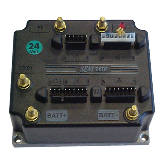
Page 12: Description Of Sem-Zero Connectors
MENU 3.4 DESCRIPTION OF SEM-ZERO CONNECTORS. PIN REFERENCE DESCRIPTION HOURMETER Output hourmeter; it controls a load to -BATT. Maximum output current 200mA. B+ Supply into logic downstream of 10A fuse & key switch. Negative main contactor coil. NEMB Negative electro-brake. -
Page 13: Description Of Power Connections
MENU PIN REFERENCE DESCRIPTION Common positive supply for micro-switch SR1, SR2, (+BATT). Input for 1 speed reduction. It should be connected to C1 by micro-switch, active LOW. Input for 2 speed reduction. . It should be connected to C1 by micro-switch, active LOW. -
Page 14: Mechanical Drawing & Dimensions
MENU 3.6 MECHANICAL DRAWING & DIMENSIONS Page 14... -
Page 15: Programming & Adjustments Using Digital Console
4.1 ADJUSTMENTS VIA CONSOLE Adjustment of Parameters and changes to the chopper’s configuration are made using the Digital Console. The Console is connected to the “E” connector of the SEM-Zero Chopper. Pay attention to the polarity of the Console Connector when connecting to the chopper. -
Page 16: Description Of Standard Console Menu
MENU 4.3 DESCRIPTION OF STANDARD CONSOLE MENU Page 16... -
Page 17: Sem-Zero: Cabling And Configuration
MENU 5 SEM-ZERO: CABLING AND CONFIGURATION 5.1 POWER DIAGRAM Page 17... -
Page 18: Connections
MENU 5.2 CONNECTIONS Page 18... -
Page 19: Description Of Programmable Functions (Options)
MENU 5.3 DESCRIPTION OF PROGRAMMABLE FUNCTIONS (OPTIONS). Using the CONFIG MENU of the console, it is possible to select from the following options: SUBMENU “SET OPTIONS”: HOUR COUNTER: - RUNNING: The counter registers travel time only. - KEY ON: The counter registers when the key switch is Closed. The A1 output for external hourmeter operates according to internal hourmeter. - Page 20 MENU Flow Chart showing how to make changes to Configuration Menu using Digital Con- sole. (Standard Eprom CK ULTRA fitted). 1) Opening Zapi Menu. 2) Press Top Left & Top Right Buttons simultaneously to enter the Config.Menu. 3) The Display will show : 4) Press ROLL UP (Top Left Button) until SET OPTIONS appears.
-
Page 21: Description Of Parameters That May Be Programmed
MENU 5.4 DESCRIPTION OF PARAMETERS THAT MAY BE PROGRAMMED In addition to the Configuration, Parameter settings may be made by Zapi using stand- ard default settings, settings to Customer Specifications, or the customer may make changes according to the application, using a Digital Console. - Page 22 MENU 17 WEAK DROPOUT = This Parameter fixes a limit on the Armature Current above which the Field Current is increased linearly up to the Nominal Field Current (in proportion to the armature current). 18 FIELD NOM. CURR. = Nominal Field Current. This parameter fixes the minimum Field Current when the potentiometer is between 0% and 60% without total conduc- tion of the Armature.
-
Page 23: Table Of Adjustments
MENU 5.5 TABLE OF ADJUSTMENTS The following Table shows the different values that the SEM2 Parameters may be adjusted to. A suitable acceleration performance assumes: FIELD CURR. NOM is set to level 5, and MAX SPEED (Fwd or Rev) is set to level 9. PROGRAMMED LEVEL PARAMETERS UNIT... - Page 24 MENU Flow Chart showing how to make Programme changes using Digital Console fitted with Eprom CK ULTRA. 1) Opening Zapi Display. 2) Press ENTER to go into the General Menu. 3) The Display will show : 4) Press ENTER to go into the Parameter Change facility.
-
Page 25: Sem-Zero Traction Standard Wiring Diagrams
MENU 5.4 SEM-ZERO TRACTION STANDARD WIRING DIAGRAMS Page 25... -
Page 26: Sequence For Sem-Zero Traction Settings
5.5 SEQUENCE FOR SEM-ZERO TRACTION SETTINGS. When the Key Switch is Closed, if no Alarms or Errors are present, the Console Display will be showing the Standard Zapi Opening Display. If the chopper is not Configured to your requirements, follow the Sequence detailed on Page 20. -
Page 27: Sem-Zero Diagnostics
MENU 6 SEM-ZERO DIAGNOSTICS The following list shows likely problems associated with the flashing RED LED. N° FLASHES MESSAGE NOTES Logic failure #1: Problem with Logic or Line Contactor. Watch-dog: Logic board and/or software failure. EEPROM KO: Problem with EEPROM or Logic. -
Page 28: Analysis Of Alarms Displayed On The Console
MENU 6.1 ANALYSIS OF ALARMS DISPLAYED ON THE CONSOLE LOGIC FAILURE #1 This test is carried out at the start-up. Possible cause: failure of the logic board WATCH DOG The test is executed at the key turn-on, at the stand-by and on running. Possible causes: a) Watch-dog hardware circuit not OK;... - Page 29 MENU VFIELD NOT OK This test is made at standby with the Line Contactor open. In this condition the voltages on both the connections of field must be to around ½ VBatt. This alarm is generated if the field voltage is different from this value. Possible causes: d) Frame fault on the motor to chassis;...
- Page 30 MENU 15 CONTACTOR CLOSED This check is made during the initial diagnosis. With the coil of the line contactor de- energized, the capacitors should not be charged, unless there is divert resistor across the power poles. Possible causes: a) The line contactor power poles are welded. b) This alarm could be generated even if the line contactor has opened, but there is a problem with either the field circuit, or a problem detected by the safety micro- processor.
-
Page 31: Tester Description Of The Functions
MENU 6.2 TESTER DESCRIPTION OF THE FUNCTIONS The most important input or output signals can be measured in real time using the TESTER function of the console. The Console acts as a multimeter able to read volt- age, current and temperature. The following definition listing shows the relative meas- urements : 1) BATTERY VOLTAGE: level of battery voltage measured at the input to the key switch. - Page 32 MENU Flow Chart showing how to use the TESTER function of the Digital Console. 1) Opening Zapi Display. 2) Press ENTER to go into the General menu. 3) The Display will show : 4) Press either ROLL UP or ROLL DOWN button until TESTER MENU appear on the display.
-
Page 33: Description Of The Console Save Function
9) Press ENTER to commence SAVE routine. 10) You can see the items that are being stored whilst the SAVE routine is happening. 11) When finished, the Console shows : 12) Press OUT to return to the Opening Zapi Display. Page 33... -
Page 34: Description Of Console Restore Function
13) You can see the items that are being stored in the chopper memory whilst the RESTORE routine is happening. 14) When finished the Console displays : 15) Press OUT to return to the Opening Zapi Display . Page 34... -
Page 35: Description Of Alarms Menu
10) When you have finished looking at the Alarms, press OUT to exit the ALARMS menu. 11) The Display will ask CLEAR LOGBOOK ? 12) Press ENTER for yes, or OUT for NO. 13) Press OUT to return to the Opening Zapi Display. Page 35... -
Page 36: Description Of Console Program Vacc Function
11) Select the Reverse Direction and repeat Item 10. 12) When finished , press OUT. 13) The Display will ask : ARE YOU SURE ?. 14) Press ENTER for yes, or OUT for NO. 15) Press OUT again to return to the Opening Zapi Menu. Page 36... -
Page 37: Recommended Spare Parts For Sem-Zero
MENU 7 RECOMMENDED SPARE PARTS FOR SEM-ZERO Part Number Description C16519 Protected 150A Fuse. C16503 Protected 200A Fuse C16520 6.3A 5x20mm Control Circuit Fuse P99060 Red LED C12372 8 Way Molex Connector C12416 6 Way Molex Connector C12371 3 Way Molex Connector... -
Page 38: Periodic Maintenance To Be Repeated At Times Indicated
During periodic checks, if a technician finds any situation that could cause damage or compromise safety, the matter should be bought to the attention of a Zapi Agent imme- diately. The Agent will then take the decision regarding operational safety of the ma- chine. - Page 39 MENU ELECTRONIC INDUSTRIAL DEVICES 42028 - POVIGLIO - (R.E.) - Via Parma, 59 - ITALIA Tel. (0522) 960050 (r.a.) - Tlx. 530021 AINDRE I - Fax (0522) 960259 INSTALLATION AND USER MANUAL CHOPPER SEM-ZERO...
Need help?
Do you have a question about the SEM-Zero and is the answer not in the manual?
Questions and answers