Table of Contents
Advertisement
Introduction .......................................................................................................... 3
1
System components ..................................................................................... 4
1.1
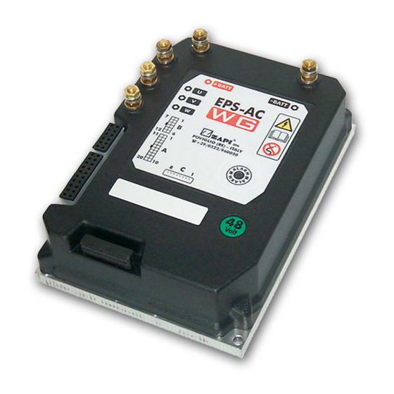
Steering servo motor control unit .......................................................... 4
1.2
Steer angle position potentiometer ....................................................... 5
1.3
Operator console ................................................................................... 5
1.4
AC steering servo motor ....................................................................... 5
1.5
Steering handle ..................................................................................... 5
1.6
Motor shaft encoder .............................................................................. 6
2
Electrical specifications ............................................................................... 7
2.1
Battery voltage range ............................................................................ 7
2.2
Steer motor current range ..................................................................... 7
2.3
Command device specifications ............................................................ 7
2.3.1 Tacho generator or stepper motor ............................................... 7
2.3.2 Automatic centering potentiometer .............................................. 8
3
Mechanical specifications ............................................................................ 9
4
System description ..................................................................................... 10
4.1
Manual steering with tacho-generator or stepper motor ..................... 10
4.2
Automatic centering............................................................................. 10
5
Jumpers description ................................................................................... 11
6
Power connection diagram ........................................................................ 13
6.1
Electrical drawing ................................................................................ 14
6.1.1 Tacho-generator steering ........................................................... 14
6.1.2 Stepper motor steering ............................................................... 15
6.1.3 Tacho-generator steering with automatic centering ................... 16
6.1.4 Stepper motor steering with automatic centering ....................... 17
6.1.5 Interface description ................................................................... 18
7
One shot installation procedure ................................................................ 20
8
Description of connectors .......................................................................... 21
8.1
CNB connector .................................................................................... 21
8.2
CNA connector .................................................................................... 23
9
Setting the steering ..................................................................................... 25
9.1
Tacho-generator or stepper motor controlled steering ........................ 25
9.2
Automatic centering............................................................................. 25
9.3
Steer angle indicator gauge ................................................................ 26
10 Zapi hand set description ........................................................................... 27
10.1 Manual mode steering option - hand set function map ....................... 28
hand set function map ......................................................................... 29
automatic centering) ............................................................................ 32
10.6 Main menu: "Tester" functions list ....................................................... 33
10.7 Config menu: "Set options" functions list ............................................. 35
Indice
Page
Page 1
Advertisement
Table of Contents

Related Manuals for Zapi EPS-AC


Summary of Contents for Zapi EPS-AC
-
Page 1: Table Of Contents
Tacho-generator or stepper motor controlled steering ......25 Automatic centering................25 Steer angle indicator gauge ..............26 10 Zapi hand set description ................27 10.1 Manual mode steering option - hand set function map ....... 28 10.2 Manual mode steering option and automatic centering - hand set function map ................. - Page 2 10.8 Config menu: "Adjustments" functions list ........... 37 10.9 Config menu: "Set model" ..............40 10.10 Maximum current adjustment .............. 40 11 EPS-AC alarm list ..................41 11.1 Analysis of alarms displayed on console ..........41 11.1.1 One blink alarms ..............41 11.1.2 Two blinks alarms ..............
-
Page 3: Introduction
Improved safety and operation are provided by having two microprocessor: the first of them performs operations and a second one executes supervisor functions. The microprocessors combined with the ZAPI hand held controller make servicing easy and direct, reducing adjustment and troubleshooting time. Increased steering motor performance and reduced noise levels are achieved by using MOSFET technology. -
Page 4: System Components
1 SYSTEM COMPONENTS The EPS_AC equipment consists of the following parts: 1.1 STEERING SERVO MOTOR CONTROL UNIT It consists of a control unit using the logic marked ADCZPA0D which operates the AC motor for both manual and automatic centering steering. There are three different control units available: 1) A 24/36Vbatt unit provides a maximum current of 70Amps. -
Page 5: Steer Angle Position Potentiometer
1.2 STEER ANGLE POSITION POTENTIOMETER To execute an automatic centering operation, a multiturn 5K potentiometer must be mounted directly on the end of the output shaft of the steering gear reduction box. This potentiometer measures the angle of the MDU directly. The full range of possible output is approximately 0÷5Vdc. -
Page 6: Motor Shaft Encoder
1.6 MOTOR SHAFT ENCODER This device is optional (not necessary). The Eps-Ac can receive an encoder (CNA #6, #16, #17 and #7) directly connected to the steering motor shaft. This is an option for a special application. E.g. fine steering speed control, safety improvement etc. A typical manual controlled steering with automatic centering does not require an encoder;... -
Page 7: Electrical Specifications
2 ELECTRICAL SPECIFICATIONS 2.1 BATTERY VOLTAGE RANGE Battery voltage input ranges for different releases of the control unit: 24/36 24-36 Vdc 48 Vdc 48/80 48-80 Vdc 2.2 STEER MOTOR CURRENT RANGE Imax ≤70Aac. Adjustable with the hand held controller (HARDWARE 24/36 SETTING) Imax ≤70Aac. -
Page 8: Automatic Centering Potentiometer
Tacho generator - mechanical specification 2.3.2 Automatic centering potentiometer The potentiometer fixed on the steering gear box output shaft should be a 5K conductive plastic potentiometer. A multi-turn potentiometer is suggested to ensure negligible mechanical play. The feedback angle potentiometer should rotate approximately ensure 80% of its total travel, corresponding to 180 degrees of steering angle. -
Page 9: Mechanical Specifications
3 MECHANICAL SPECIFICATIONS Page 9... -
Page 10: System Description
The control logic sets the steer servo-motor in motion at a speed that increases with the speed of the steering wheel. Steering sensitivity and maximum speed are adjustable by using the ZAPI hand held controller. -
Page 11: Jumpers Description
5 JUMPERS DESCRIPTION Three are three jumpers it is possible to configure. J7: This jumper selects the active level on the travel demand inputs. Travel demands are connected in the CNA #5 and CNA #15 positions. They are used in the automatic centering to restart steering always when the truck is moving. - Page 12 J8: This jumper selects the optional encoder supply voltage. When J8 is closed between pins No. 1 and 2, the encoder supply is 16Vdc; when closed between pins No. 2 and 3, the encoder supply is 5Vdc. J2: This is a two pin jumper. When closed the safety contact is internally grounded. When open the safety contact is floating and should be externally polarized (see 8.1).
-
Page 13: Power Connection Diagram
6 POWER CONNECTION DIAGRAM Note: Reversing Battery positive and negative will damage the unit. Page 13... -
Page 14: Electrical Drawing
6.1 ELECTRICAL DRAWING 6.1.1 Tacho-generator steering Page 14... -
Page 15: Stepper Motor Steering
6.1.2 Stepper motor steering Page 15... -
Page 16: Tacho-Generator Steering With Automatic Centering
6.1.3 Tacho-generator steering with automatic centering Page 16... -
Page 17: Stepper Motor Steering With Automatic Centering
6.1.4 Stepper motor steering with automatic centering Page 17... -
Page 18: Interface Description
CNB Pin #2 (16Vdc supply) and CNB Pin #8 (device driver collector). d) The Eps-Ac provides an internal safety contact accessible through connector CNB pin #7 and CNB pin # 1. It should be used to stop the traction and to enable an electromechanical brake when a steering alarm occurs. - Page 19 e) The automatic centering request must have an NPN open collector output (see fig. 6.1.5.2). So it should assume the model of an open or closed switch with respect to GND. External pull-up is not required. The automatic centering request may be level or edge triggered depending on the AUT INP ACTIVE setting (see 10.7.7).
-
Page 20: One Shot Installation Procedure
Clockwise (Clockwise for a truck with a leading MDU) the value on the wiper is increasing. This value may be measured in two ways. Use the Zapi hand held controller through the TESTER MENU' (see 10.6.3). The second way is to use a DC voltmeter connected to the steering angle feedback pot. -
Page 21: Description Of Connectors
8 DESCRIPTION OF CONNECTORS 8.1 CNB CONNECTOR This is the second (lower potential) safety switch connection.The first connection is on Pin #7. If jumper J2 is closed, the Pin # 1 is ground referenced and NK1 is at ground (GND) potential. If jumper J2 is open, NK1 is floating. - Page 22 This is the first (higher potential) safety switch connection.The second connection is on Pin #1. This normally open contact is closed by switching on the key. When the key switch is On, the contact opens in case of steering alarm. If Jumper J2 is closed, ground is provided on pin 7 whenever the key switch is on and there is no alarm.
-
Page 23: Cna Connector
8.2 CNA CONNECTOR NPOT This is the lower voltage connection for the steer feedback potentiometer. It's internally connected to GND through a 470 Ohms resistance. PPOT This is the higher voltage connection for the steer feedback potentiometer. It's internally connected to a 5Vdc reference through a 470 Ohms resistance . - Page 24 ZAPI hand control for SET MAX FB POT. 4.5Vdc corresponds to the steer angle feedback pot voltage that was memorized using the ZAPI hand control for SET MIN FB POT . See 10.7.6 to reverse the turning direction displayed.
-
Page 25: Setting The Steering
9 SETTING THE STEERING Use the ZAPI hand set to adjust the manual steering settings. 9.1 TACHO-GENERATOR OR STEPPER MOTOR CONTROLLED STEERING The following procedure should be used only after "One Shot Installation Procedure" in Section 7 is completed. Carry out the procedure in the following sequence. -
Page 26: Steer Angle Indicator Gauge
9.3 STEER ANGLE INDICATOR GAUGE If a steer angle indicator gauge with Leds is applied then you will also need to perform the following steps for the gauge to respond correctly: 1) Use SET MIN FB POT on the hand set to memorize the steer angle feedback pot voltage for maximum Clockwise rotation of the Drive Unit (see 10.8.12). -
Page 27: Zapi Hand Set Description
10 ZAPI HAND SET DESCRIPTION This section describes the ZAPI hand set functions. Numbers inside the triangles correspond to the same number on the hand set keyboard buttons shown in the figure below. The orientation of the triangle indicates the way to the next function. -
Page 28: Manual Mode Steering Option - Hand Set Function Map
10.1 MANUAL MODE STEERING OPTION - HAND SET FUNCTION MAP Page 28... -
Page 29: Manual Mode Steering Option And Automatic Centering - Hand Set Function Map
10.2 MANUAL MODE STEERING OPTION AND AUTOMATIC CENTERING - HAND SET FUNCTION MAP Page 29... -
Page 30: Main Menu "Parameters List
10.3 MAIN MENU "PARAMETERS LIST" The parameters are slightly different between tacho-generator, tacho-generator with automatic centering and pot steering option. (the stepper motor application has the same hand set map as the tacho-generator configuration) After modifyng a parameter, memorize it with the hand set by pushing the "4" (OUT) button and the "3"... - Page 31 Through the Can comunication, the traction chopper supplies the truck speed information to the EPS-AC. The EPS-AC can reduce the steering motor speed as the truck speed increase. Aux function 3 make it possible to alter the amount of the max steering speed reduction with increasing truck speed.
-
Page 32: Parameters In Set Model 1 (Tacho-Generator Or Stepper Motor And Automatic Centering)
8) AUX FUNCTION 4 Has the same purpose as the previous parameter. The only difference is the aux function 4 varies the value of the steering speed when the hand-wheel is turning slowly. 10.5 PARAMETERS IN SET MODEL 1 (TACHO-GENERATOR OR STEPPER MOTOR AND AUTOMATIC CENTERING) All the parameters in the section 10.3 are adopted also for the tacho-generator (or stepper motor) and automatic centering model. -
Page 33: Main Menu: "Tester" Functions List
10.6 MAIN MENU: "TESTER" FUNCTIONS LIST The TESTER functions list is common for applications with or without the automatic centering model. Each TESTER function provides the measurement, executed by the software, of the specified parameter. Descriptions of each TESTER function are given below. - Page 34 12) CW LIMIT LEVEL Provides in real time the information that the steer angle feedback potentiometer has overcome the SET MAX FB POT value (see 10.8.13). 13) ACW LIMIT LEVEL Provides in real time the information that the steer angle feedback potentiometer has overcome the SET MIN FB POT value (see 10.8.12).
-
Page 35: Config Menu: "Set Options" Functions List
10.7 CONFIG MENU: "SET OPTIONS" FUNCTIONS LIST The SET OPTIONS functions list is used for all the steering options. These options modify the system configuration on user request. A description of each option follows in the list below. Page 35... - Page 36 1) HOUR COUNTER There are two possible value options for what will appear in the root menu hand set display. - RUNNING = Run time when the steering is enabled. - KEYON = Time counted continously when the logic is supplied. 2) MICRO CHECK This feature is to support the debugging activity option.
-
Page 37: Config Menu: "Adjustments" Functions List
8) AUX FUNCTION #1 Sets the steering mode after the feedback pot has reached the final position (it is for only the two pots steering and the automatic centering options). - Level 0 = The steering motor is turned on when a travel demand is active. - Level 1 = The steering motor is alternatively turned off (for 15sec.) and on (for 3sec.) disregarding the travel demand state. - Page 38 5) ADJUSTMENT #4 Provides the second phase current gain: it can be acquired or hand adjusted pushing the right side buttons (factory adjusted). 6) SET BATTERY TYPE Specify the battery you have through this option. This setting is used for the flux compensation when the COMPENSATION parameter is set to Level 1 or 2.
- Page 39 Is for the stepper motor application only. This voltage is auto acquired the first time the EPS-AC is switched on and corresponds to the voltage level in the D line (CNB- 3) when the stepper motor is standing. Typical 2.5V.
-
Page 40: Config Menu: "Set Model
Enter the ALARM CONFIG MENU. Push at the same time the two right side buttons. This sequence will enter the hidden ZAPI MENU. Roll up and down (buttons 1 and 2) until the "HARDWARE SETTING" appears on the hand set display. Enter it and change with the right side buttons the maximum current setting. -
Page 41: Eps-Ac Alarm List
11 EPS-AC ALARM LIST 11.1 ANALYSIS OF ALARMS DISPLAYED ON CONSOLE Here is the alarm list 11.1.1 One blink alarms MICRO SLAVE KO Cause: When no number is specified it means the Master Microprocessor (MM) has detected a status signal coming from the supervisor (SM) that dos't agree with the present comand values. - Page 42 MICRO SLAVE #5 Cause: Means the SM has detected the motor is standing while the command is not at rest. Remedy: If the alarm occurs permanently, it is necessary to substitute the logic. MICRO SLAVE #6 Cause: Means the SM has detected the motor turning direction is opposite to the tacho command.
- Page 43 If the alarm does not occur due to wrong wiring, it is necessary to substitute the logic. The failure could be in a mechanical relay defect or in a fault of the relay driver. 10) KS CLOSED Cause: It occurs when the MM has detected the SM safety contact closed before it's commanded.
-
Page 44: Two Blinks Alarms
It's a warning that occurs if the traction module is not connected or if there is some problems on the Can-Bus line. Remedy: Check the Can-Bus lines. If you want the EPS-AC working without Can-Bus comunication turn to "Absent" the hardware setting "Can- Bus" with the hand set. -
Page 45: Three Blinks Alarms
11.1.3 Three blinks alarms STEER SENSOR KO Cause: It occurs when the tacho-generator is open or short circuited. Remedy: Check the tacho-generator wires and measure the tacho-generator resistance (should be close to 22 Ohms). If the problem is not due to wiring, replace the tacho-generator. -
Page 46: Four Blinks Alarms
Execute a CLEAR EEPROM operation. To do it Enter the ALARM CONFIG MENU. Push at the same time the two right side buttons. This sequence will enter the hidden ZAPI MENU. Roll up and down (buttons 1 and 2) until the "CLEAR EEPROM" appears on the hand set display. -
Page 47: Six Blinks Alarms
11.1.6 Six blinks alarms STBY I HIGH Cause: It occurs if the rest state current signals (measured on the phases U and W) are not in the window 2.5±0.3Vdc after switching on the key and 2.5±0.15Vdc when in the steady state. These voltage are measured between D46 and D45 anodes and gnd. - Page 48 LOGIC FAILURE #4 Cause: It occurs when in the rest state the Vu-Vw phase motor voltage is high: that means the voltage between D48 anode and gnd is not in the window (Vu-Vw)0±0.25Vdc (see Fig. 11.1.6.2). Remedy: If the alarm occurs permanently, it is necessary to substitute the logic.
-
Page 49: Safety Controls And Their Use
12 SAFETY CONTROLS AND THEIR USE 12.1 SAFETY CONTROLS IN TACHO-GENERATOR AND AUTOMATIC CENTERING STEERING The following malfunctioning conditions are tested on electrical manual steering: Safety on motor wires broken. Safety on failures of the steering wheel tacho-generator or stepper motor. Safety on the presence of current when the steering motor is at rest. -
Page 50: Safety On The Presence Of Phase Voltage When The Steering Motor Is At Rest
12.5 SAFETY ON THE PRESENCE OF PHASE VOLTAGE WHEN THE STEERING MOTOR IS AT REST The microprrocessor logic continuously tests the phase voltage amplifiers output at rest and if they are other than 2.5Vdc±0.25Vdc, causes an alarm. These voltage are measured between D47 and D48 anodes and gnd (see Fig 11.1.6.2). -
Page 51: Periodic Maintenance
OEM parts. Any potential problem discovered by the service technician periodically checking the equipment that could lead to additional vehicle damage must be communicated to ZAPI technical staff or the technical sales network so that corrective action and an appropriate decision regarding continued operation of the equipment can be made. - Page 52 COSTRUZIONE APPARECCHIATURE ELETTRONICHE - OLEODINAMICHE - INDUSTRIALI COSTRUZIONE APPARECCHIATURE ELETTRONICHE - OLEODINAMICHE - INDUSTRIALI 42028 - POVIGLIO - (R.E.) - Via Parma, 59 - ITALIA Tel. +39 0522 960050 (r.a.) - Fax +39 0522 960259 - e-mail: zapi@zapispa.it EPS-AC OPERATING AND USER...
Need help?
Do you have a question about the EPS-AC and is the answer not in the manual?
Questions and answers