
Related Manuals for SIGMATEK SCP 111


Summary of Contents for SIGMATEK SCP 111
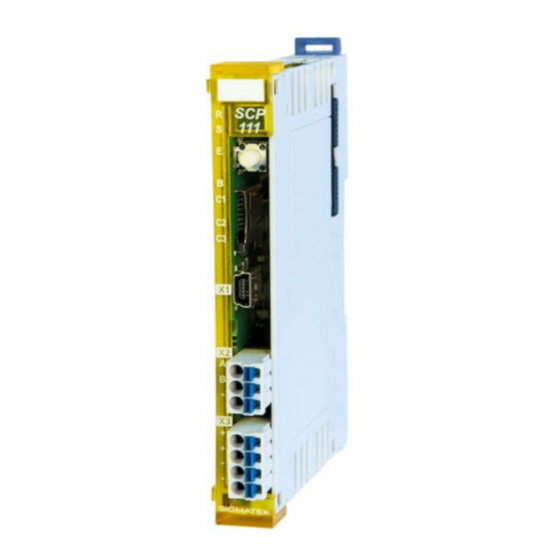
- Page 1 SCP 111 S-DIAS Safety CPU Module Instruction Manual Date of creation: 20.05.2015 Version date: 05.12.2023 Article number: 20-890-111-E...
- Page 2 (print, photocopy, microfilm or in any other process) without the express permission. We reserve the right to make changes in the content without notice. The SIGMATEK GmbH & Co KG is not responsible for technical or printing errors in the handbook and assumes no responsibility for damages that occur through use...
- Page 3 Safety System Handbook, see homepage With the SCP 111, Safe process data is transmitted with its own safety protocol (FSoE). Therefore, the SCP 111 cannot be used with a CSCP 011/012, SCP 010/011 in a Safety project.
-
Page 4: Table Of Contents
SCP 111 S-DIAS SAFETY CPU MODULE Contents Introduction ................6 Target Group/Purpose of this Operating Manual ...... 6 Important Reference Documentation ......... 6 Contents of Delivery ..............6 Basic Safety Guidelines ............7 Symbols Used ................7 Disclaimer ..................9 General Safety Directives ............ - Page 5 S-DIAS SAFETY CPU MODULE SCP 111 Type Plate ................19 Technical Data ............... 20 Performance Data ............... 20 Electrical Requirements ............. 21 6.2.1 Module Supply (Input) ............... 21 6.2.2 S-DIAS Bus/Safety Supply (Output) ..........22 Miscellaneous ................24 Environmental Conditions ............24 Mechanical Dimensions ............
- Page 6 SCP 111 S-DIAS SAFETY CPU MODULE Configuring a Safety CPU with the mSD Card ......35 10 Error Response ..............36 10.1 Restart Errors ................36 10.2 Configuration Distribution Error ..........37 10.3 Troubleshooting ................. 38 10.4 Troubleshooting with the SafetyDesigner ....... 38 10.5...
- Page 7 S-DIAS SAFETY CPU MODULE SCP 111 17 Disposal ................. 46 05.12.2023 Page 5...
-
Page 8: Introduction
Please see our website for our hotline number and business hours. Important Reference Documentation • Safety System Handbook This and additional documents can be downloaded from our website or obtained through support. Contents of Delivery 1x SCP 111 Page 6 05.12.2023... -
Page 9: Basic Safety Guidelines
S-DIAS SAFETY CPU MODULE SCP 111 Basic Safety Guidelines Symbols Used The following symbols are used in the operator documentation for warning and danger messages, as well as informational notes: DANGER Danger indicates that death or serious injury will occur, if the specified measures are not taken. - Page 10 SCP 111 S-DIAS SAFETY CPU MODULE CAUTION Danger for ESD-sensitive components. Les signes de danger pour les composants sensibles aux décharges électrostatiques. INFORMATION Information Provides important information on the product, handling or relevant sections of the documentation, which require attention.
-
Page 11: Disclaimer
It does not guarantee properties under the warranty. Please thoroughly read the corresponding documents and this operating manual before handling a product. SIGMATEK GmbH & Co KG is not liable for damages caused through, non-compliance with these instructions or applicable regulations. -
Page 12: General Safety Directives
SCP 111 S-DIAS SAFETY CPU MODULE General Safety Directives The Safety Directives in the other sections of this operating manual must be observed. These instructions are visually emphasized by symbols. INFORMATION According to EU Directives, the operating manual is a component of a product. - Page 13 S-DIAS SAFETY CPU MODULE SCP 111 CAUTION Handle the device with care and do not drop or let fall. Prevent foreign bodies and fluids from entering the device. The device must not be opened! Manipulez l’appareil avec précaution et ne le laissez pas tomber.
-
Page 14: Designated Use
The Safety functions implemented in the product are designed for use with safety applications in a SIGMATEK control and meet the required conditions for safe operation according to SIL 3, HFT 1 n compliance with EN 62061 and according to PL e, Kat. 4 in compliance with EN ISO 13849-1. -
Page 15: Software/Training
S-DIAS SAFETY CPU MODULE SCP 111 Une installation CEM correcte est également incluse dans l’utilisation prévue. Non-designated use consists of: • any changes made to the module or the use of damaged modules. • use of the module inconsistent with the technical margins described in this operating manual or the specifications defined in the technical data. -
Page 16: Security
SCP 111 S-DIAS SAFETY CPU MODULE IT Security S-DIAS safety modules were developed for integration into a network protected against unauthorized access. For example, the following dangers can affect the network: • Unauthorized access • Data manipulation • and many other IT security violations It is the responsibility of the operator to protect the safe connection between S-DIAS modules against unauthorized access. -
Page 17: Standards And Directives
S-DIAS SAFETY CPU MODULE SCP 111 Standards and Directives Residual Risks CAUTION The following residual risks for the product must be included in the system integrator's risk assessment: • Release of non-environmentally safe substances, emissions and unusual temperatures • Possible effects of information technology devices Les risques résiduels suivants pour le produit doivent être inclus dans... -
Page 18: Functional Safety Standards
EN ISO 13849-2 - Safety of machinery — Safety-related parts of control systems — Part 2: Validation 4.3.2 EU Conformity Declaration EU Declaration of Conformity The product SCP 111 conforms to the following European directives: • 2006/42/EG Machine Directive • 2014/30/EU Electromagnetic Compatibility (EMC Directive) •... -
Page 19: Safety-Relevant Parameters
S-DIAS SAFETY CPU MODULE SCP 111 Safety-Relevant Parameters 4.4.1 Mounting Position Horizontal 0-55 °C Ambient Temperature CPU Module Safety Parameters Safety Levels SCP 011 = 1,4E-10 (1/h) SIL 3 according to EN IEC 62061 MTTF = 2689 years PL e / Cat. 4... -
Page 20: Compatibility
SCP 111 S-DIAS SAFETY CPU MODULE Compatibility The safety-related component, SCP 111, is supported with Firmware version 423 or Build No, 1348 and higher of the Safety Designer. INFORMATION Compatibility In regard to compatibility with the S-DIAS Safety component, section "Compatibility with S-DIAS Safety Components"... -
Page 21: Type Plate
S-DIAS SAFETY CPU MODULE SCP 111 Type Plate HW: Hardware version SW: Software version 05.12.2023 Page 19... -
Page 22: Technical Data
SCP 111 S-DIAS SAFETY CPU MODULE Technical Data Performance Data ARM Cortex M µController Addressable Safety I/O modules S-DIAS Safety bus: 16 Data memory Type SRAM Memory 24 kbytes Program memory Type Flash Memory 224 kbytes Remnant memory for parameter... -
Page 23: Electrical Requirements
S-DIAS SAFETY CPU MODULE SCP 111 Electrical Requirements 6.2.1 Module Supply (Input) Supply voltage +18-30 V DC, typically +24 V DC UL: Class 2 or LVLC Current, internal consumption typically 90 mA internal consumption (2) (3) maximum 1.4 A Current consumption... -
Page 24: S-Dias Bus/Safety Supply (Output)
Safety number lower than S01.03.01 is integrated with Safety I/O modules in the S-DIAS system (blue modules), the voltage increase of the +24 V supply of the SCP 111 must not happen later than 100 ms after the voltage supply of the S-DIAS supply modules, otherwise it can happen, that the SCP 111 does not recognize the Safety I/O modules on the Safety bus. - Page 25 S-DIAS SAFETY CPU MODULE SCP 111 05.12.2023 Page 23...
-
Page 26: Miscellaneous
SCP 111 S-DIAS SAFETY CPU MODULE Miscellaneous Article number 20-890-111 20-890-111-X (polymer coated printed circuit board) Standard UL 508 (E247993) Approbations , CE, TÜV Austria type-tested Mission time 20 years Environmental Conditions Storage temperature -20 ... +85 °C Environmental temperature 0 ... -
Page 27: Mechanical Dimensions
S-DIAS SAFETY CPU MODULE SCP 111 Mechanical Dimensions 05.12.2023 Page 25... -
Page 28: Connector Layout
SCP 111 S-DIAS SAFETY CPU MODULE Connector Layout INFORMATION The connections of the +24 V supply (X3: pin 1 and pin 2) or the GND supply (X3: pin 3 and pin 4) are internally bridged. To supply the module, only one connection to a +24 V pin (pin 1 or pin 2) and a GND pin (pin 3 or pin 4) is required. -
Page 29: Status Leds
S-DIAS SAFETY CPU MODULE SCP 111 Status LEDs The LED display lights continuously to indicate that the in- and outputs are active. green Indicates The time-limited (LED "S" on) operation mode or Or unlimited time ("S" LED off) operation mode. -
Page 30: Applicable Connectors
SCP 111 S-DIAS SAFETY CPU MODULE Applicable Connectors Connectors: X1: USB Type Mini-B (not included in delivery) X2 – X3: Connectors with spring terminals (included in delivery) The spring terminals are suitable connecting ultrasonically compacted (ultrasonically welded) strands. Connections: Stripping length/Sleeve length:... -
Page 31: Label Field
S-DIAS SAFETY CPU MODULE SCP 111 Label Field Manufacturer Weidmüller Type MF 10/5 CABUR MC NE WS Weidmüller article number 1854510000 Compatible printer Weidmüller Type Printjet Advanced 230V Weidmüller article number 1324380000 05.12.2023 Page 29... -
Page 32: Validation Button
SCP 111 S-DIAS SAFETY CPU MODULE Validation Button With the validation button S1, several commands as well as the validation can be executed: • Acknowledging an error and exiting the error status • Deleting a configuration from the Safety CPU •... -
Page 33: Command Selection Sequence
S-DIAS SAFETY CPU MODULE SCP 111 9.1.2 Command Selection Sequence After the Start sequence, the desired command is selected. This selection is made with button presses in the following time intervals: Minimum press duration is 200 ms, maximum is approximately 3 seconds; the minimum pause between individual button presses is 200 ms, the maximum is 10 seconds. -
Page 34: Overview Of Commands
SCP 111 S-DIAS SAFETY CPU MODULE Overview of Commands The number of button presses corresponds to the number of light pulses in LED B during the End sequence. Commands Number of button LED C1 LED C2 LED C3 presses QUIT_ERROR... - Page 35 S-DIAS SAFETY CPU MODULE SCP 111 Executed Command function Status after command execution command QUIT_ERROR A possible error is cancelled in the Safety CPU SW-RESET *) and all safety modules required by the Safety CPU and the error status is ended.
-
Page 36: Handling The Microsd Card (Msd)
SCP 111 S-DIAS SAFETY CPU MODULE Handling the microSD Card (mSD) An mSD card can only be written on with the Safety Designer. A detailed description can be found Safety System Handbook (Link: https://www.sigmatek- automation.com/fileadmin/user_upload/downloads/Safety-Systemhandbuch-eng.pdf). A Safety project, which was programmed with the SafetyDesigner, can be stored on an mSD card. -
Page 37: Configuring A Safety Cpu With The Msd Card
INFORMATION A microSD card with a memory capacity of 1 Gigabyte is available from SIGMATEK under the article number 12-630-101 Only microSD cards that support version 2.0 or higher of the "SDA Physical Layer Specification" (SDA=SD Card Association) can be used. -
Page 38: Error Response
SCP 111 S-DIAS SAFETY CPU MODULE 10 Error Response In the event of an error, please consult the chapter "LED Displays", as important information on the runtime status of the system can be derived from the status an error display. Since errors in general are of a complex nature, do not perform a diagnosis based on the LEDs alone (consult the corresponding chapter in the Safety System Handbook as well). -
Page 39: Configuration Distribution Error
S-DIAS SAFETY CPU MODULE SCP 111 During restart, the Safety CPU first runs the POST (Power On Self Test). In the POST, whether the Safety CPU is configured or not is determined. If the Flash memory in the Safety CPU is empty, it changes to the service mode and switches the status LED (ST) to continuously on. -
Page 40: Troubleshooting
SCP 111 S-DIAS SAFETY CPU MODULE 10.3 Troubleshooting • Check all modules in the system for completeness and Type conformity • Check that all modules are error-free • Check all connector cables • Cancel the error with the QUIT_ERROR command If the Safety CPU remains in the error status after the QUIT_ERROR command has been executed, it must be retested using the SafetyDesigner. -
Page 41: Wiring Guidelines
S-DIAS SAFETY CPU MODULE SCP 111 11 Wiring Guidelines The input filters, which suppress noise signals, allow operation in harsh environmental conditions. A careful wiring method is also recommended to ensure error-free function. The following installation guidelines should be observed: •... -
Page 42: Shielding
The low-ohm shielding is either connected at the entry to the control cabinet or directly before the SCP 111 over a large surface (cable grommets, grounding clamps)! Noise signals can therefore be prohibited from reaching the electronics and affecting the function. -
Page 43: Assembly/Installation
S-DIAS SAFETY CPU MODULE SCP 111 12 Assembly/Installation 12.1 Check Contents of Delivery Ensure that the contents of the delivery are complete and intact. See chapter Contents of Delivery. INFORMATION On receipt and before initial use, check the device for damage. If the device is damaged, contact our customer service and do not install the device in your system. -
Page 44: Mounting
SCP 111 S-DIAS SAFETY CPU MODULE 12.2 Mounting The S-DIAS modules are designed for installation into the control cabinet. To mount the modules a DIN-rail is required. The DIN rail must establish a conductive connection with the back wall of the control cabinet. The individual S-DIAS modules are mounted on the DIN rail as a block and secured with latches. - Page 45 S-DIAS SAFETY CPU MODULE SCP 111 Recommended minimum distances of the S-DIAS modules to the surrounding components or control cabinet wall: a, b, c … distances in mm (inches) 05.12.2023 Page 43...
-
Page 46: Supported Cycle Times
SCP 111 S-DIAS SAFETY CPU MODULE 13 Supported Cycle Times The SCP 111 can be accessed via the S-DIAS bus with different bus cycle times. 13.1 Cycle Times below 1 ms (in µs) x= supported 13.2 Cycle Times equal to or higher than 1 ms (in ms) -
Page 47: Transport/Storage
S-DIAS SAFETY CPU MODULE SCP 111 14 Transport/Storage INFORMATION This device contains sensitive electronics. During transport and storage, high mechanical stress must therefore be avoided. For storage and transport, the same values for humidity and vibration as for operation must be maintained! Temperature and humidity fluctuations may occur during transport. -
Page 48: Maintenance
SCP 111 S-DIAS SAFETY CPU MODULE 16 Maintenance INFORMATION During maintenance as well as servicing, observe the safety instructions from chapter 2 Basic Safety Directives. 16.1 Service This product was constructed for low-maintenance operation. 16.2 Repair INFORMATION In the event of a defect/repair, send the device with a detailed error description to the address listed at the beginning of this document. - Page 49 S-DIAS SAFETY CPU MODULE SCP 111 Documentation Changes Change date Affected Chapter Note page(s) 08.07.2015 3.2 Electrical Requirements Added note 04.08.2015 Info Cover Translation from German added 15.10.2015 11, 12 3.2 Electrical Requirements Table split 20.01.2016 3.2 Electrical Requirements updated 21.01.2016...
- Page 50 Standards added 04.05.2021 3.3 Miscellaneous Article number -X added 19.10.2021 3.1 Performance Data Extended 05.12.2023 Introduction SCP 111-X added 3. IT Security Chapter added 6.3 Miscellaneous Mission time added 6.4 Environmental Conditions Noise emissions added 13 Supported Cycle Times Description added...
Need help?
Do you have a question about the SCP 111 and is the answer not in the manual?
Questions and answers