SKF LINCOLN P653S Installation And Maintenance Manual
Hide thumbs
Also See for LINCOLN P653S:
- User and maintenance instructions (56 pages) ,
- User and maintenance instructions (44 pages) ,
- User and maintenance instructions (40 pages)
Table of Contents
Advertisement
Advertisement
Table of Contents

Related Manuals for SKF LINCOLN P653S


Summary of Contents for SKF LINCOLN P653S
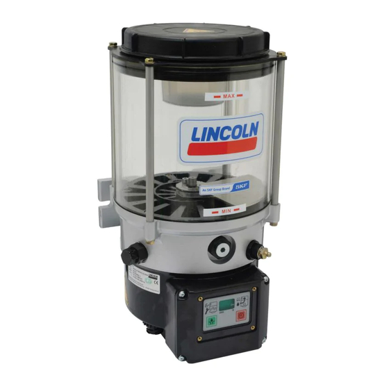
- Page 1 Installation and maintenance guide Electric operated Centro–Matic oil pump P653S Models 80127 ( 4L ) 80128 ( 8L ) Date of issue May 2016 Publication number 404542C Read manual prior to installation or use of product. Keep manual nearby for future reference.
-
Page 2: Table Of Contents
Contents Introduction Explanation of symbols used . . . . . . . . . . . . . . . . . . . . . . . . . . . . . User’s responsibility . -
Page 3: Introduction
Introduction Explanation of User’s responsibility W a r n i n g symbols used To ensure the safe operation of the unit, Signalizes a dangerous situation, which The following description standards are used the user is responsible for the following: can lead to severe or light personal in this manual: injury, if the precautionary measures are... -
Page 4: Safety Instructions
Safety instructions Appropriate use Exclusion of liability General safety instructions The manufacturer of the P653S pump will • Pump P653S is designed for safe The electric Centro-Matic oil pump P653S not accept any liability for damages caused operation . has been designed for the automatic lubri- •... -
Page 5: Operation, Maintenance And Repair
Operation, Important! W a r n i n g maintenance and Risk of bursting if the reservoir is Pump P653S must be installed by overfilled! When filling the reservoir by qualified personnel . The connection of means of pumps with a large delivery the 120 V AC must be done according volume do not exceed the maximum filling mark . -
Page 6: Installation
Installation Installation and • Any safety equipment already installed on maintenance of C a u t i o n the vehicle: – should not be modified or made Use only supply line hose and fittings hydraulic hoses ineffective; that are appropriate for the pro- –... - Page 7 General Description Pump P653S Fig. 1 The P653S pump is designed for single line • pumps mineral oil (per approved list) at Single–line pump P653S, no follower (S) parallel Centro–Matic type lubrication temperatures from (Note: Low–level control † fig. 12 and 13, 32 to 122 °F page 17) systems .
- Page 8 Industrial (S) Pump Application: Time (TC) or count Number of Low–level F1 fault relay; (31) F2 fault relay; (31) switch combinations Industrial control (cc) transducers . control; switch to ground to ground AS09 Industrial Switch to ground Switch to ground AS11 Industrial Switch to ground...
-
Page 9: Description Of Operation
Description of operation Pump operation Lube cycle/pressurization Fig. 2 • The motor turns the cam (7) clockwise to Disassembled pump housing – view from Drive start lubrication cycle . As soon as pump the bottom starts to operate, the display rotating seg- •... -
Page 10: Pump Element Operation
Pressure control/hold Fig. 4 Fig. 7 time/vent cycle Activated vent cycle diagram Rotating segmented display during venting (counterclockwise) Pump with internal pressure transducer Use only pump elements designed for operation in the P653S pump . Internal pressure transducer is factory set to close at 1450 psi (80 bar) . - Page 11 Fig. 9 Holding time (H1) • Internal pressure transducer must stay Pump element Z7 for internal lubricant cross porting closed for 15 consecutive seconds before going to H2 . If internal pressure transduc- er opens during the 15 seconds, pump will restart and run until internal pressure transducer closes .
-
Page 12: Filling Reservoir With Oil
Venting cycle Fig . 12 • After the pump completes the preset hold 1 stirring paddle time and the pump maintains the speci- fied pressure, the controller will initiate a vent cycle . The vent cycle will last for ten seconds . -
Page 13: Keypad And Display
Keypad and display Membrane keypad Test display of the • A test display is made when voltage is membrane key pad applied: all segments and decimal points are illuminated for 2 seconds . Fig. 14 Fig. 15 Notice P653S membrane key pad Green segment right, power supply “on”... - Page 14 Fig . 17 Fig . 19 • If the power supply is interrupted during the lubricating time the operating time Green circulating illuminated segment, Display of a low-level indication. will start at the beginning after switching lubricating time, pump is running. power on again .
- Page 15 Malfunctions Fig . 22 Fig . 24 • If there is no feedback from the pressure Display of the malfunction E3, failure to Operator key to trigger an additional transducer within 12 minutes of pumping vent at the pump lubrication cycle time, the pump switches off immediately .
- Page 16 Factory settings for parameters Programming steps Factory setting Description Count Thousands, hundreds Count Tens, unit Output of both fault relays no (normally open) nc (normally closed) Two options for signalling a fault O1 (Option 1) F1 relay contact a) Low–level fault will cause F1 contact to repeatedly open and close . b) Pressure fault will cause F1 contact to close and stay closed .
- Page 17 Factory settings for parameters Programming steps Factor setting Description Pause time - 0 to 59 hours . Pause time - 0 to 59 minutes . Output of both fault relays . NO (normally open) . NC (normally closed) . Two options for signalling a fault: o1 (option 1) F1 relay contact .
-
Page 18: Acknowledging A Fault
Acknowledging a fault To acknowledge a malfunction: Display Press • The flashing display changes into continu- ous light by pressing the button (acknowl- edging) . By acknowledging the fault sig- < 2 seconds nal, the flashing E1, E3, or LL changes into permanent light . -
Page 19: Programming The Pump
Programming the pump Step 1 Step 2 Notice Pump power must be on to start programming . Display Function Key for modifying the parameters in the programming step P1: Setting of hours When releasing the two buttons, the cur- rently set value appears . Press Example .: factory-set value: ………... - Page 20 Step 3 Step 4 Press button so that “P4“ appears in the display . Display Press When releasing the button, the currently set value appears in the display (here the factory–set value NO, normally open con- tact) . On a fault condition the alarm contact will close .
- Page 21 Step 8 Step 9 F2 fault relay’s contact will close on a pressure fault and stay closed . Both of these contacts can be used for Display Press remote signaling . Display Press Press push button to change to option 1 . Step 7 Display Press...
- Page 22 Step 10 Notice After completion of the program- ming, check the parameter settings in Display Press the review mode . Programming of the pump with pressure transducer is complete . Completing the programming Press button . “P -” is displayed . Notice Always carry out the program- ming completely in order to save the new...
-
Page 23: Review Of Pump Parameters
Review of the pump parameters after one sec . after one sec . after one sec . 12 . (hours) after one sec . Press the button > 2 seconds . after one sec . (remaining pause time) Notice 5 . - Page 24 Operating mode after one sec . after one sec . External pressure transducer will open at 900 psi . after one sec . after one sec . after one sec . after one sec . Ed Indicates software version . The next two displays will indicate soft- ware version .
-
Page 25: Technical Data
Technical data Electrical data for AC pump Incoming voltage 100 to 240 V AC Packing (cardboard box) Maximum current 1 .7 A Frequency 47 to 63 Hz Attaching parts Output from power supply 24 V DC at 5 A Operating Instructions External fuse 3 A (time delay) Installation... - Page 26 Jumper settings for 653 pump PCB TC – Time control CC – Count control F1 – Fault relay for low level Without jumper – Time control F2 – Fault relay for pressure S – Industrial (AC) WIth jumper – count control M –...
-
Page 27: Schematic Of P653S Pump
Schematic of P653S pump To bearings To atmosphere P653S pump To bearings 1 Pumping housing (3 pump elements) 2 Motor 3 Controller, key board with display 4 Internal pressure transducer (P . T .) 5 Internal vent valve 6 Reservoir with low level control 7 Pressure relief, 1,450 psi (100 bar) external 8 High pressure supply line 9 Injectors... -
Page 28: Dimensions
Fig. 45 Dimensions P653S, 4 liter reservoir 0 .433 in . (11 mm) 6 .85 in . (174 mm) 7 .1 in . (120 mm) 9 .25 in . (235 mm) 9 .5 in . (240 mm) Reservoir with stirring paddle: A2 = 18 .4 in . (467 mm) - Page 29 Fig. 46 Dimensions P653S, 8 liter reservoir 0 .433 in . (11 mm) 6 in . (154,5 mm) 7 in . (180 mm) 9 .25 in . (235 mm) 9 .5 in . (240 mm) Reservoir with stirring paddle: B2 = 20 in . (508 mm)
- Page 30 Connections for 110-230 V AC 50/60 Hz P652S pump Black Black 3 A fuse White Blue Neutral 24 V DC Grounding Green Green/yellow wire Brown 24 V DC Pressure 0.5 to 4.5 V Machine Pressure Signal Transducer switch transducer Black Pump on light Yellow...
- Page 32 Troubleshooting Mode of failure Solution Pump motor does not run . No green right corner segment lit on display Check power supply and fuses . († fig. 18, page 15) Pump does not deliver lubricant but runs if manual lube switch (3) Check count switch for 24 V DC pulse .
-
Page 33: Parts List
Parts list Item Description Part no . Quantity Item Description Part no . Quantity Valve svte - 100 r1/4 +nip .S2520-1/4 1 . 624-77642-1 1 Cover, housing 275666 bag) Socket GDM 3011 J black UL, CSA 236-10834-5 1 Screw, sock, hex . 8 .8 M 5x 16 C 201-12016-6 Connector 7 poles (AC pump) 664-34569-1 1... - Page 35 Reservoir Reservoir 48, 49...
-
Page 36: Warranty
Lincoln industrial Special limited 5 year warranty– This warranty gives you specific legal standard warranty limited oil meters, limited fluid control rights . You may also have other rights that valves, aod (air–operated diaphragm vary by jurisdiction . pumps) Standard Limited warranty Customers not located in the Western Hemisphere or East Asia: Please contact Lincoln warrants the 712 series Control... - Page 37 This page left intentionally blank...
- Page 38 This page left intentionally blank...
- Page 39 This page left intentionally blank...
- Page 40 . Every care has been taken to ensure the accuracy of the information contained in this publication but no liability can be accepted for any loss or damage whether direct, indirect or consequential arising out of the use of the information contained herein . SKF PUB LS/I1 13347/2 EN · May 2016 · Form 404542C . lincolnindustrial.com...
Need help?
Do you have a question about the LINCOLN P653S and is the answer not in the manual?
Questions and answers