Table of Contents
Advertisement
Quick Links
Advertisement
Table of Contents

Related Manuals for SKF PPS30 Series


Summary of Contents for SKF PPS30 Series
- Page 1 Assembly Instructions Air operated piston pump unit Series PPS30 Created on: 30.01.2023 Document no.: 951-170-250-EN Version: Read these instructions before installation or start-up of the product and keep them readily available for later consultation!
- Page 2 The special technical documents were prepared following Annex VII part B. Upon justifiable request, these special technical documents can be forwarded electronically to the respective national authorities. The authorized company for the compilation of the technical documentation is SKF (U.K.) Limited, 2 Canada Close, Banbury, Oxfordshire, OX16 2RT, GBR.
- Page 3 Appendix to ACP Declaration of Incorporation in accordance with 2006/42/EC, Annex II, No. 1 B Description of the essential health and safety requirements according to 2006/42/EC, Annex I, which have been applied and fulfilled: Table 1 Appendix to Declaration of Incorporation No.: Essential health and safety requirement Applicable:...
- Page 4 Table 1 Appendix to Declaration of Incorporation No.: Essential health and safety requirement Applicable: Fulfilled: 1.5.12 Laser radiation 1.5.13 Emissions of hazardous materials and substances 1.5.14 Risk of being trapped in a machine 1.5.15 Risk of slipping, tripping, or falling 1.5.16 Lightning Servicing...
-
Page 5: Masthead
Training www.skf.com/lubrication We conduct detailed training in order to enable maximum safety and efficiency. We recommend taking advantage of this Berlin Plant training. For further information, contact your authorized SKF Motzener Strasse 35/37 dealer or the manufacturer. 12277 Berlin Germany Tel. -
Page 6: Table Of Contents
1. Safety instructions ................8 6.5 Lubrication line connection ........... 25 1.1 General safety instructions ............. 8 6.6 Assembly of the lubrication lines using SKF quick 1.2 General electrical safety instructions ........8 couplings ..................25 1.3 General behaviour when handling the product ....8 6.6.1 Installing the metal pipe .......... -
Page 7: Safety Alerts, Visual Presentation, And Layout
1. Instruction steps: These indicate a chronological sequence Safety alerts, visual of instruction steps. The numbers of the steps are in bold and are followed by a period. If a new activity follows, the presentation, and layout numbering starts again at “1.” –... -
Page 8: Safety Instructions
Only • If protective and safety equipment has to be dismantled, it original SKF spare parts and SKF accessories may be used. must be reassembled immediately after finishing the work, • Any unclear points regarding proper condition or correct and then checked for correct function. -
Page 9: Foreseeable Misuse
during transport, installation, start-up, operation, maintenance, 1.9 Painting plastic components and repair and disassembly. seals The painting of any plastic components and seals of the 1.6 Foreseeable misuse products described is prohibited. Completely mask or remove Any usage of the product other than as specified in this manual plastic components before painting the main machine. -
Page 10: Note On The Type Plate
1.15 Note on UKCA marking NOTE In accordance with the results of the workstation risk The UKCA conformity marking confirms the assessment, additional labels (e.g., warnings, safety signs, product’s conformity with the applicable legal prohibition signs, or labels in accordance with CLP/GHS) are provisions of Great Britain. -
Page 11: First Start-Up, Daily Start-Up
• All parts are correctly installed 1.20 First start-up, daily start-up • All warning labels on the product are fully present, visible, and Ensure that: undamaged • All safety devices are fully present and functional • Illegible or missing warning labels are immediately replaced •... -
Page 12: Lubricants
Solid lubricants may only be used after prior consultation with make the selection in consultation with the supplier of the SKF. When solid lubricants are used in lubrication systems, the lubricant. If you have no or little experience in selecting following rules generally apply: lubricants for lubrication systems, please contact us. -
Page 13: Overview, Functional Description
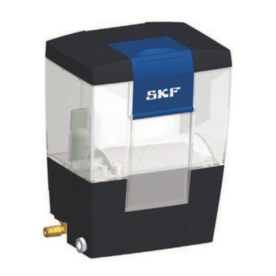
3. Overview, functional description Fig. 3 Overview of PPS30 piston pump unit Legend to Figure 3: 1 Filling flap 2 Reservoir 3 Pneumatic piston pump 4 Compressed air supply port 5 Connection for electrical signal 6 Lubrication line connections 7 Installation surface with M6 installation thread inserts 8 Level switch NOTICE Property damage... -
Page 14: General Functional Description
The housing and reservoir are made on plastic, providing 3.1 General functional description reduced weight compared to conventional pump units. Thanks to its compact design and easy installation, the PPS30 piston NOTE pump unit can be used to set up single-line centralized The numbers in parentheses below refer to positions on the lubrication systems very easily and with little mounting effort. -
Page 15: Functional Description Of Single-Line Systems
• The lubricant lines are relieved (relief pressure approx. becomes contaminated by impurities in the lubricant, the unit 0.5 bar) must be sent in to SKF. Therefore, fill using only clean, • The actuating piston (Fig. 5/1) is in its upper end position uncontaminated lubricants. -
Page 16: Start Of Lubrication Cycle
3.4.2 Start of lubrication cycle 3.4.3 End of lubricating cycle Fig. 6 Fig. 7 Start of lubrication cycle End of lubricating cycle Legend to Figure 6: 1 Pneumatic input Legend to Figure 7: 2 Pneumatic output 1 Actuating piston 3 Outlet valve 2 Pressure relief valve 4 Inlet suction valve 3 Inlet suction valve... - Page 17 The piston metering devices in the single-line system switch over and are ready for the next lubricating cycle.
-
Page 18: Technical Data
4. Technical data 4.1 General technical data Table 4 General technical data Mounting position Vertical Ambient temperature + 10 °C to + 50 °C Operating temperature + 10 °C to + 50 °C Delivery rate Up to 30 cm /stroke Operating pressure Up to 26 bar - see Figure 8 Pumped medium... - Page 19 Fig. 8 Inlet pressure/operating pressure Legend to Figure 8: X Inlet pressure (bar) Y Operating pressure (bar) Table 7 Inlet pressure/operating pressure Inlet pressure (bar) Operating pressure (bar) Approx. 17 Approx. 21 Approx. 23 Approx. 26 Table 8 Requirements for compressed air Requirement Values Inlet pressure...
-
Page 20: Product Code
4.2 Product code P P S 30 - 2 x x x x x x x x x Pump Pneumatically operated Lubricant Oils and fluid greases Delivery rate 30 cm /stroke generation 2. generation Lubricant reservoir 1,5 liters 1.5 liters with oil filling strainer Fill level switch min. -
Page 21: Delivery, Returns, Storage
5.5 Storage conditions for products filled 5. Delivery, returns, storage with lubricant 5.1 Delivery For products filled with lubricant, the permitted storage temperature range is: After receipt of the shipment, it must be inspected for any minimum + 5 °C [+41 °F] shipping damage and for completeness according to the maximum... -
Page 22: Assembly
A Section A-A (without pump) 6. Assembly The product should be protected from humidity and vibration 6.1 Setup and attachment and should be mounted so that it is easily accessible, allowing all further installation work to be done without difficulty and allowing the piston pump unit to be filled easily later. -
Page 23: Port Dimensions, Assembly Holes, And Minimum Mounting Dimensions
6.2 Port dimensions, assembly holes, and minimum mounting dimensions Fig. 12 Port dimensions, assembly holes, and minimum mounting dimensions Legend to Figure 12: A View A B Section B-B (without pump) OUT Pump outlet, left, right, and rear INPUT Compressed air connection port Minimum mounting dimensions: C (Width): 220 mm D (Height) 450 mm... -
Page 24: Installation Of The Product
5. Pass hexagon socket screws (4x) acc. to DIN EN ISO 4762 6.3 Installation of the product M6x...-8.8 with associated washers (4x) acc. to Fig. 13 DIN EN ISO 7090 6-200HV through customer-provided fixing holes and apply the screws to the M6 installation thread inserts of the piston pump unit. -
Page 25: Lubrication Line Connection
6.6 Assembly of the lubrication lines contact with moving parts using SKF quick couplings 6.5 Lubrication line connection The SKF quick couplings are available in designs for metal pipes or plastic tubing. CAUTION With the design for metal pipes, there is a choice available Risk of slipping and injury between pipe versions with and without claw groove. -
Page 26: Installing The Metal Pipe
(Fig. 16/2) functions properly. the pipe using appropriate fastening hardware such as pipe clamps, to prevent the pipe from slipping out of the SKF quick disconnect coupling. 2. Insert the pipe (Fig. 15/1) fully into the collet (Fig. 15/2) of the SKF quick disconnect coupling until the pipe passes the first O-ring (Fig. -
Page 27: Connection Of Electrical Pressure Switch And Fill Level Switch
6.7 Connection of electrical pressure Legend to Figure 17: switch and fill level switch BU blue BK black Fig. 17 BN brown WH white 1 Voltage + 10-36 V DC (pressure switch) 2 Pressure switch signal (DS) (pressure switch) 3 0V voltage 0 V DC (fill level switch) 4 "Pre-warning for min. -
Page 28: Venting The Centralized Lubrication System
6.8 Venting the centralized lubrication system Fig. 18 Single-line centralized lubrication system Legend to Figure 18: 1 Filling flap 2 "MAX" marking 3 Ends of the main pipes 4 Inlet to the first metering device 5 PPS30 piston pump unit A PPS30 piston pump unit B Lubrication points C Single-line metering device... -
Page 29: First Start-Up
7.1 Inspections before first start-up 7. First start-up Table 9 NOTICE Checklist (before first start-up) Lack of lubrication Damage due to excessively low or no lubricant Check the lubricant level. The lubricant may only be supplied without bubbles Electrical connection established correctly ... -
Page 30: Operation
8. Operation 8.1 General NOTICE Manufacturer's instructions Damage from ignoring manufacturer's instructions Observe the instructions from the machine manufacturer regarding the lubricants that are to be used NOTICE System malfunction System malfunction due to contaminated lubricant Only fill using clean lubricant and an appropriate device. Contaminated lubricants lead to system malfunctions. -
Page 31: Maintenance And Repair
NOTE SKF shall not be held liable for damages resulting from improperly performed assembly, maintenance, or repair work on the product. Careful and regular maintenance is required in order to detect and remedy possible faults in time. -
Page 32: Cleaning
< 10. Cleaning WARNING Serious injury from contact with or inhalation of hazardous substances WARNING Compressed air Wear personal protective equipment. Observe the Injury from working on pressurized system safety data sheet (SDS) of the hazardous components substance. Avoid contaminating other objects or The product described here is pressurized during the environment during cleaning. -
Page 33: Faults, Causes, And Remedies
Compressed air Injury from working on pressurized system NOTE components Only original SKF spare parts may be used. Unauthorized The product described here is pressurized during alterations to products and the use of non-original spare operation. The product must therefore be parts and accessories are prohibited. - Page 34 Table 12 Commissioning, product, and system malfunctions Cause Remedy Pneumatic piston pump runs with • System pressure is too low • Check inlet pressure: 4.5 to 6 bar difficulty, builds up no pressure or does • Screw union of pneumatic feed line is required so very slowly defective...
-
Page 35: Repairs
12. Repairs 13. Shutdown, disposal < 13.1 Temporary shutdown WARNING Risk of injury Temporary shutdowns should be done by a course of action to At a minimum, the following safety be defined by the operator. measures must be taken before any 13.2 Permanent shutdown, disassembly repairs: Permanent shutdown and disassembly of the product must be... -
Page 36: Spare Parts
14. Spare parts Spare parts may be used exclusively for replacement of identical defective parts. Modifications with spare parts on existing products are not allowed. Fig. 19 Sealing flap Table 13 Sealing flap Designation Weight [g/pc.] Order No. Spare part kit, flap & 995-901- information label... -
Page 37: Accessories
15. Accessories 15.1 Fittings and accessories Fig. 20 Fittings and accessories Table 14 Fittings and accessories Designation Weight [g/pc.] Order No. Control valve PPS30 - kit 995-901-062 3/2 directional control valve PPS30 - kit 995-901-063 Oil filter PPS30 169-400-405 PPS30 unit with optional built-in oil filling strainer PPS30- 22xxxxxxxx Wall mounting PPS30 - kit... -
Page 38: Other Accessories
Add the desired length, e.g. 30 meters, to the order No. Order example: WVN716-RO6×1.25×30M NOTE You can find additional technical specifications in the following leaflets: Electric Plug and Socket Connectors Leaflet 1-1730-EN Lubricant metering devices for SKF MonoFlex systems Leaflet 1-5001-EN Transport of Lubricants in Centralized Lubrication Systems Leaflet 1-9201-EN... -
Page 39: Appendix
16. Appendix 16.1 China RoHS Table Table 16... - Page 42 ® SKF and Lincoln are registered trademarks of the SKF Group. ™ eLube is a trademark of the SKF Group. © SKF Group 2023 Reprint or reproduction of the contents of this information - even in part - is permitted only with SKF's prior written consent.
Need help?
Do you have a question about the PPS30 Series and is the answer not in the manual?
Questions and answers