
Subscribe to Our Youtube Channel
Related Manuals for SKF LINCOLN P623S


Summary of Contents for SKF LINCOLN P623S
- Page 1 Installation instructions Lubrication pump P623S following machinery directive 2006/42/EC for single-line lubrication systems 951-171-014-EN Version 01 2016/03/14...
-
Page 2: Ec Declaration Of Incorporation Following Machinery Directive 2006/42/Ec
EC Declaration of incorporation EC Declaration of incorporation following machinery directive 2006/42/EC, annex II, part 1 B The manufacturer, SKF Lubrication Systems Germany GmbH, Walldorf Facilities, Heinrich-Hertz-Str. 2-8, DE - 69190 Walldorf, hereby declares that the partly completed machinery Designation:... -
Page 3: Legal Disclosure
Disclaimer The manufacturer shall not be held respon- In order to provide a maximum of safety Manufacturer's facilities and economic viability, SKF carries out de- sible for damages caused by: Head Office ○ non appropriate use tailed training courses. It is recommended Walldorf Facilities that the training courses are attended. -
Page 4: Table Of Contents
Table of contents Table of contents EC Declaration of incorporation following machinery directive 2006/42/EC .................... 2 Legal disclosure ...................... 3 Explanation of symbols, signs and abbreviations ..........7 Lubricants ................... 17 Safety instructions .................9 General information ................17 General safety instructions ..............9 Selection of lubricants ................17 General behaviour when handling the product ........ - Page 5 Table of contents 4.8.3 Relay circuit board ................39 Initial start-up ................54 4.8.4 Configuration of the control pcb ............40 Inspections prior to initial start-up .............54 Type identification code ................42 Inspections during initial start-up ............54 Delivery, returns, and storage ............ 43 Order ...................
- Page 6 Table of contents 12.6 Tests after replacement of the power supply board ......69 Electrical connections ..............73 12.6.1 Visual check ...................69 15.1 Cable colours following IEC60757 ............73 12.6.2 Electrical safety test ................69 15.2 Wire allocation of the connectors ............73 12.6.3 Electrical functionality test ..............69 15.3 Assignment of the circuit diagrams to the pump type identification code .............73...
-
Page 7: Explanation Of Symbols, Signs And Abbreviations
Explanation of symbols, signs and abbreviations Explanation of symbols, signs and abbreviations The following abbreviations may be used within these instructions. Symbols within safety notes mark the kind and source of the hazard. General warning Dangerous electrical voltage Risk of falling Hot surfaces Unintentional intake Crushing hazard... - Page 8 Explanation of symbols, signs and abbreviations Abbreviations and conversion factors regarding °C degrees Celsius °F degrees Fahrenheit approx. approximately Kelvin Ounce i.e. that is Newton fl. oz. fluid ounce etc. et cetera hour inch poss. possibly second pounds per square inch if appl.
-
Page 9: Safety Instructions
1. Safety instructions 1. Safety instructions 1.2 General behaviour when handling the 1.1 General safety instructions product ○ The owner must ensure that safety infor- ○ The product may be used only in aware- ○ Safety-related protective and emergency mation has been read by any persons en- ness of the potential dangers, in proper devices must not be removed, modified trusted with works on the product or by... -
Page 10: Intended Use
1. Safety instructions 1.3 Intended use 1.5 Painting of plastic parts ○ to supply, transport, or store hazardous Supply of lubricants within a single- Painting of any plastic parts or seals of the substances and mixtures in accordance line system following the specifications, described products is expressly prohibited. -
Page 11: Notes Related To The Ce Marking
1. Safety instructions 1.7 Modifications of the product 1.6 Notes related to the CE marking 1.9 Inspections prior to delivery CE marking is effected following the re- The following inspections were carried out Unauthorized conversions or modifica- prior to delivery: quirements of the applied directives: tions may result in unforeseeable impacts ○... -
Page 12: Markings On The Product
Model: ________________________________ ervoir lid being open P. No. _________________________________ Marks the protective conductor connection S. No. _________________________________ (CW/YY) _______________________________ Calendar week/year of construction SKF Lubrication Systems Germany GmbH Model: P623S P. No.: 645-xxxxx-x S. No.: xxxxxxxxxxxx pmax: xxx bar / xxxx psi... -
Page 13: Persons Authorized To Operate The Pump
1. Safety instructions 1.14 Briefing of external technicians 1.13 Persons authorized to operate the 1.16 Order pump Prior to commencing the activities, external The following must be observed during technicians must be informed by the opera- commissioning and operation. ○ Any information within this manual and tor of the company safety provisions, the 1.13.1 Operator applicable accident prevention regulations... -
Page 14: Transport, Installation, Maintenance, Malfunctions, Repair, Shutdown, Disposal
1. Safety instructions ○ Carry out electrical connections only ac- ○ Ensure through suitable measures that 1.18 Transport, installation, maintenance, malfunctions, repair, shutdown, movable or detached parts are immobi- cording to the information in the valid disposal. lized during the work and that no limbs wiring diagram and taking the relevant can be caught in between by inadvertent regulations and the local connection con-... -
Page 15: Initial Commissioning, Daily Start-Up
1. Safety instructions ○ All components used must be designed 1.19 Initial commissioning, daily start-up 1.20 Cleaning according to the maximum operating ○ Risk of fire and explosion when using Ensure that: pressure and the maximum respectively ○ All safety devices are completely available inflammable cleaning agents. -
Page 16: Residual Risks
1. Safety instructions 1.21 Residual risks Residual risk Possible in life cycle Prevention/ remedy Personal injury/ material damage due to Keep unauthorized persons away. No people may remain under suspended A B C G H K falling of raised parts loads. -
Page 17: Lubricants
2.2 Selection of lubricants 2.3 Material compatibility Lubricants are used specifically for cer- SKF considers lubricants to be an element Lubricants must generally be compatible tain application purposes. In order to fulfil of system design. A suitable lubricant is se- with the following materials: ○... -
Page 18: Ageing Of Lubricants
(e.g. "bleeding"). on the packaging have to be Please contact SKF. if you have further observed. questions regarding lubricants. - 18 - 951-171-014 Version 01... -
Page 19: Overview, Functional Description
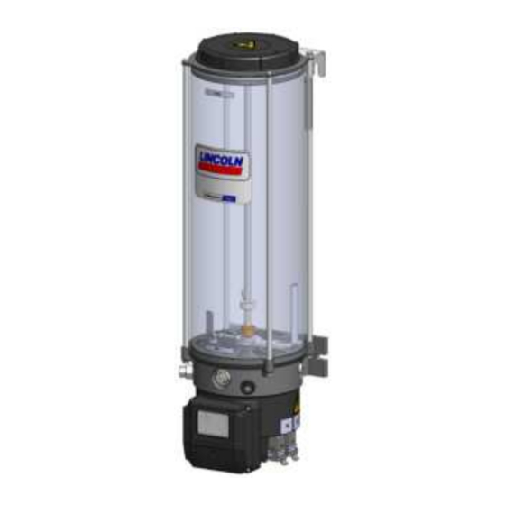
3. Overview, functional description 3. Overview, functional description Overview Fig. 1 1 reservoir The lubricant is stored in the reservoir. De- pending on the pump version there are differ- ent types of reservoirs and reservoir sizes. 1.1 Reservoir venting device It provides air for the reservoir while the pump is operating and supplying lubricant. - Page 20 3. Overview, functional description Overview Fig. 2 4. Pump elements The pump is operated with 3 pump elements cross-ported to one outlet. 5. Filler fitting It serves to fill the reservoir via a suitable filler pump with a corresponding connection. 6.
- Page 21 3. Overview, functional description 7. ProProtect indication Overview Fig. 3 If the LED (7) is green, the ProProtect protec- tion up to 8 kV is available. If the LED (7) is off despite existing operating voltage, only the standard protection level (EN 61000-6-4) is available.
- Page 22 3. Overview, functional description Overview Fig. 4 8. 2 Follower plate (in case of pumps with fol- lower plate) The follower plate (8) rests on the lubricant and presses it down in the direction of the pump ele- ments by spring force. As a result the suction behaviour of the pump improves.
- Page 23 3. Overview, functional description Overview Fig. 5 17 Membrane keypad The membrane keypad (17) with display is the primary operating and display element of the pump. It offers the following functions: 18 Display Display of operating states, error codes and programming parameters 19 Set button Confirming faults in the operating mode...
-
Page 24: Functioning Principle Of The Intermittent Low-Level Indication
3. Overview, functional description 3.1 Functioning principle of the intermittent low-level indication The intermittent low-level indication operates free of contact. Its main components are the following: ○ firmly positioned magnetic switch (I) inside of the reservoir bottom ○ flexible guide plate (II) connected to the stirring paddle with a magnet (III) and a control cam (IV) If the reservoir is filled with a lubrication grease suitable for the intermittent low-level indication and the pump is operating, then the guide plate (II) is de- flected by the resistance of the lubrication grease. -
Page 25: Functioning Principle Of Pressurization, Holding Time And Pressure Relief
3. Overview, functional description 3.2 Functioning principle of pressuri- zation, holding time and pressure relief Reaching and holding the operating Phase 1 Pressurization: pressure via the pressure holding When the pause time (PT) has lapsed, the pump Functional chart, see the following time (PHT) ensures that the single- starts pressurization within the pressurization page... - Page 26 3. Overview, functional description Functional diagram P623S Fig. 6 Legend Internal pressure course External pressure course Operating pressure in case of in- Œ ternal pressure switches/ sensors Operating pressure in case of ex- Ž ternal pressure switches/ sensors Switch-back pressure in case of internal pressure switches/ sensors Switch-back pressure in case of ex- ternal pressure switches/ sensors...
-
Page 27: Overview Of The Displays
3. Overview, functional description 3.3 Overview of the displays Starting process Fault signals Fault signal EP A fault of the membrane keypad or the display is Functional test after switching on. pending. All segments are lit for about 2 seconds. Fault signal E1 (flashing) Fault of pressurization (internal pressure control). - Page 28 3. Overview, functional description Order Operating voltage Pause time The operating voltage of the pump is switched on After the pressure relief the pause time („br“ = break) starts Operating voltage and machine contact Holding time H1 The operating voltage and the machine contact For internal pressure sensors are switched on.
- Page 29 3. Overview, functional description Programming mode Time control Program steps P1 and P2 Hours Minutes With these program steps the pause time value is set Time control (jumper on control pcb) P1 = 0 to 59 hours P2 = 0 to 59 minutes Example: Pause time = 12 h 30 min Pulse control Pulses (x100)
- Page 30 3. Overview, functional description Programming mode Program step P7 Output signal programmed as normally open contact. Setting of the operating pressure Intermittent low-level signal, functional faults as per- Factory setting 300 bar / Display value = 30 manent signal (ON). See program step P5. Program step P8 Output signal programmed as normally closed Setting of the relief pressure ( only in case of...
- Page 31 3. Overview, functional description Example Query mode In case of a time control of the pump, the preset pause time is displayed by 2 consecutive displays. Example = 12 h 30 min (also see query mode, chapter 8.2) In case of a pulse control of the pump, the preset pause time is displayed by 2 consecutive displays.
-
Page 32: Technical Data
4. Technical data 4. Technical data 4.1 Mechanics P623S Admissible operating temperature range of the pump -25 °C to +55 °C The indicated operating temperature range of the pump presupposes the suitability of the lubricant used for the respective actually existing operat- ing temperature. -
Page 33: Nominal Output Volumes
4. Technical data 4.2 Nominal output volumes Pump element Nominal output per pump element and stroke 0.22 cc The stated nominal outputs per stroke refer to NLGI II lubricating greases at an operating temperature of + 20 °C and a backpressure of 100 bar on the pump element. -
Page 34: Useable Reservoir Volume
4. Technical data 4.3 Useable reservoir volume Regarding the reservoir version without follower plate the useable reservoir volume mainly depends on the NLGI consistency class and the operat- ing temperature of the lubricant to be used. In case of high consistency and low operating temperature normally more lubricant sticks to the inner surfaces of the reservoir and the pump and is thus no more available for being dispensed. -
Page 35: Limits Of Use Of The Intermittent Low-Level Indication
4. Technical data 4.5 Limits of use of the intermittent low-level indication The following lubricant consistencies have to be complied with in order to ensure the correct functioning of the intermittent low-level indication. Above the stated range of temperature a correct functioning of the intermittent low-level indication cannot be ensured. The inferior temperature ranges require the suitability of the lubricant for the respective temperature range. -
Page 36: Factory Settings
4. Technical data 4.6 Factory settings Program Parameters Factory setting Setting range Time control: 6 hours 0 minutes 4 min up to 59h 59 min Pause time value P1/ P2 P1 for hours / pulses (x 100) P2 for minutes / pulses (x 1) Pulse control: 10 pulses 1 to 9999 no (normally open contact) reservoir with... -
Page 37: Tightening Torques
4. Technical data 4.7 Tightening torques The stated tightening torques must be adhered to. Pump with supporting construction provided by the customer 25 Nm ± 1.0 Nm Pump element with pump housing 40 Nm ± 2.0 Nm Pressure control valve with pump element 8 Nm + 0.8 Nm Housing front cover with pump housing 2.5 Nm + 0.1 Nm... -
Page 38: Electrics
4. Technical data 4.8 Electrics: Input Rated voltage/ operating voltage range 230 - 273 V AC / 120 - 300 V DC Rated frequency/ frequency range 50-60 Hz / 0 Hz Current consumption typically 0.82 A at 230 V AC Switch-on current limitation <... -
Page 39: Control Pcb
4. Technical data 4.8.1 Control pcb Rated voltage 12 V DC / 24 V DC Output fault / readiness for operation 1 A short-circuit resistant (transistor) ≥ 200 ms Length of pulse in case of pulse control 4.8.2 Motor Operating voltage 24 V DC Nominal motor speed 20 rpm... -
Page 40: Configuration Of The Control Pcb
4. Technical data 4.8.4 Configuration of the control pcb The jumper configuration on the control pcb is done ex works following the customer's specifications. As changes of the configuration by third parties are not immediately apparent, the configuration should not be modified by the operator later on. Time or Number of pressure Setting options... - Page 41 4. Technical data Changes of the configuration will become effective only after switching the pump off and on again. Time or Number of pressure switches/ Application Low level indication Programming lock cycle control pressure sensors Normally open Normally Stationary Time Cycle without with...
-
Page 42: Type Identification Code
4. Technical data 4.9 Type identification code Structure of the type identification code The type identification code facilitates identification of P 6 2 3 S X L B O - 3 Z 7 - A C - H 1 .H 2 - S 0 8 - D S Example A important equipment features of the product. -
Page 43: Delivery, Returns, And Storage
5.3 Storage 5.4 Storage temperature range ○ In case of parts not primed with lubri- After receipt of the shipment, check the SKF products are subject to the following shipment for damage and completeness storage conditions: cant the admissible storage temperature ○... -
Page 44: Special Storage Conditions For Parts Primed With Lubricant
5. Delivery, returns, and storage 5.5.3 Storage period exceeding 18 5.5 Special storage conditions for parts cation purpose to the divider bar in such primed with lubricant way that the opposite port of the divider months bar remains open. To avoid dysfunctions consult the manufac- The conditions mentioned in the following turer before commissioning. -
Page 45: Assembly
6. Assembly 6. Assembly 6.2 Place of installation 6.1 General information ○ Possibly existing visual monitoring de- Protect the product against humidity, dust Only qualified technical personnel may vices, e.g. pressure gauges, MIN/MAX and vibrations and install it in an easily ac- install the products described in these markings or piston detectors, must be cessible position to facilitate other installa-... -
Page 46: Mechanical Connection
6. Assembly 6.3 Mechanical connection Minimum assembly dimensions Fig. 7 6.3.1 Minimum assembly dimensions Ensure sufficient space for maintenance or repair work or for assembly of further components of the centralized lubrication system by leaving a free space of at least 100 mm into each direction in addition to the stated dimensions. -
Page 47: Installation Bores
6. Assembly 6.3.2 Installation bores Mounting bores in mm Installation bores Fig. 8 Pumps with 4 l and 8 l reservoirs: 10 l 15 l 20 l Are fastened at the two lower mounting points (A). Pumps with 10 l, 15 l and 20 l reservoirs: 177.5 177.5 177.5... -
Page 48: Electrical Connection
6. Assembly Electrical connection, Fig. 9 6.4 Electrical connection WARNING Electric shock Make sure to disconnect the product from the power supply before carrying out any works on electrical components. Connect the cables in such way that no mechanical forces are transferred to the product. -
Page 49: Lubrication Line Connection
6. Assembly 6.5 Lubrication line connection ○ The lubricant flow should not be impeded Observe the following installation instruc- CAUTION tions for safe and smooth operation. by the installation of sharp elbows, angle ○ Use clean components and primed lubri- valves, gaskets protruding to the inside, Risk of falling cation lines only. -
Page 50: Programming
6. Assembly 6.6 Programming 6.6.1 Legend of the programming Notes related to the programming scheme To program the pump proceed according to Settings can be done in one direction only Program functions the following programming scheme. P1/ P2 Setting of the pause time in hours •... - Page 51 6. Assembly Programming scheme P623S Fig. 10 & > 4 S (OR) - 51 - 951-171-014 Version 01...
-
Page 52: Filling Via Filler Fitting
6. Assembly 6.6.2 Filling via filler fitting Filling via filler fitting Fig. 11 • Place filling connection of the filler pump onto filler fitting R1/4 (5). • Switch on filler pump and fill reservoir with lubricant until shortly below the MAX marking. -
Page 53: Filling Via The Reservoir Lid In Case Of Pumps Without Follower Plate
6. Assembly 6.6.3 Filling via the reservoir lid in case Filling via the reservoir lid Fig. 12 of pumps without follower plate WARNING Crushing hazard on the rotating stirring paddle. Fill- ing via the reservoir lid is allowed only after disconnecting the pump from the power supply by remov- ing it from the connection (6.2). -
Page 54: Initial Start-Up
7. Initial start-up 7. Initial start-up In order to warrant safety and function, a person assigned by the operator must carry out the following inspections. Remedy detected de- fects before the initial start-up. Deficiencies may be remedied by an authorized and qualified specialist only. Start-up check list 7.1 Inspections prior to initial start-up Electrical connection carried out correctly. -
Page 55: Order
8. Order 8. Order SKF products operate automatically to the greatest possible extent. Basically, activities during standard opera- tion are limited to the control of the filling level and the timely refilling of lubricant as well as the outside cleaning of the product in case of contamination. -
Page 56: Query Mode
8. Order 8.2 Query mode In the query mode all adjusted programming parameters of the pump are displayed one after the other. The displays change every 2 sec- onds and finish automatically after the last value was displayed. To access the operating mode, press key 20 of the membrane keypad for more than 4 seconds. -
Page 57: Flow Chart Of Query Mode In Case Of Pulse Control
8. Order 8.2.2 Flow chart of query mode in case of pulse control Course of displays in case of pulse control (configuration of the pcb) Fig. 14 x 100 x 100 > 4 S (OR) (OR) (OR) (OR) OR = logical "OR“. Corresponding to the actually adjusted parameter only one display will be displayed. -
Page 58: Cleaning
Thoroughly remove residues • Mark and secure wet areas. To do so, contact the SKF Customer Service. of cleaning agents from the • Keep unauthorized persons away. product and rinse off with clear water. -
Page 59: Maintenance
10. Maintenance Maintenance Regular and appropriate maintenance is a prerequisite to detect and clear faults in time. As it is not possible for us to exactly define the operating conditions, we cannot indicate any definite deadlines. The specific timelines have to be determined, verified at regular intervals and adapted, if necessary, by the operator based on the local operating conditions. -
Page 60: Troubleshooting
11. Troubleshooting Troubleshooting Fault table 1 Fault signal Possible cause Remedy (flashing) Low level indication The ongoing lubrication cycle will still be completed. An auto- Fill the reservoir with the specified lubricant matic restart will take place after filling only. However, an ad- ditional lubrication is possible. - Page 61 11. Troubleshooting Fault table 2 Fault Possible cause Remedy Check whether one of the indicated faults is present and rem- - Power supply to the pump is interrupted edy it in the frame of your responsibilities. - Superior machine is switched off Faults outside of your own responsibility have to be reported - Connection cable of pump is loose or defective to your superior to initiate further measures.
-
Page 62: Repairs
12. Repairs Repairs 12.1 Check pump element and replace WARNING Replace pump element Fig. 15 pressure control valve. Risk of injury The characteristics of the new Before carrying out any repair pump element must correspond work, take at least the following to the characteristics of the safety measures: pump element to be replaced... -
Page 63: Replace Membrane Keypad
12. Repairs 12.2 Replace membrane keypad To replace the membrane keypad proceed Remove the housing front cover Fig. 16 Housing front cover removed Fig. 17 as follows: • Check the new membrane keypad for ac- cordance with the documentation and the intended purpose. - Page 64 12. Repairs • Carefully loosen and remove the mem- Loosened plug of the membrane keypad Fig. 18 Remove the housing front cover Fig. 20 brane keypad (17) forward from the housing. • Guide the plug (17.1) of the new mem- brane keypad (17) from the front through the opening on the housing front cover and plug it onto the corresponding port...
-
Page 65: Replace Control Printed Circuit Board
12. Repairs 12.3 Replace control printed circuit board Remove the housing front cover Fig. 21 Remove the control pcb 22 To replace the control pcb proceed as follows: • Check the new control pcb for accordance 12.2 with the documentation and the intended purpose. -
Page 66: Replace Relay Circuit Board
12. Repairs 12.4 Replace relay circuit board Remove the housing front cover Fig. 24 Remove relay circuit board Fig. 25 To replace the relay circuit board proceed as 13.1 follows: • Check the new relay circuit board for ac- cordance with the documentation and the intended purpose. -
Page 67: Replace Power Supply Board
12. Repairs 12.5 Replace power supply board Remove housing front cover Fig. 26 Remove relay circuit board Fig. 27 To replace the power supply board proceed 13.1 as follows: • Check the new power supply board for accordance with the documentation and the intended purpose. - Page 68 12. Repairs • Place new power supply board in the lat- Power supply board Fig. 29 Power supply board moun- eral guide rails (14.1) and push it into the ted incorrectly Fig. 31 housing until you notice resistance. 14.1 14.1 •...
-
Page 69: Tests After Replacement Of The Power Supply Board
12. Repairs 12.6 Tests after replacement of the power 12.6.3 Electrical functionality test 12.6.2 Electrical safety test supply board Use measuring equipment following The electrical function test must be carried out immediately after the repair following EN 61557 for the mentioned electrical After replacement of the power supply the protection class of the electrical appara- tests. -
Page 70: Shutdown And Disposal
13. Shutdown and disposal Shutdown and disposal 13.1 Temporary shutdown 13.3 Disposal Temporarily shut the system down by: Countries within the European Union ○ switching off the superior machine. Disposal should be avoided or minimized ○ Disconnecting the product from the Dispose of or recycle electrical wherever possible. -
Page 71: Spare Parts
14. Spare parts Spare parts The spare parts assemblies may be used exclusively for replacement of identical defective parts. Modifications with spare parts on existing products are not allowed. Fig. 33 14.1 Housing front cover, assy. Designation Qty. Part number Consisting of: 545-60168-1 1 x housing front cover... -
Page 72: Control Pcb
14. Spare parts Fig. 36 14.4 Control pcb Designation Qty. Part number Consisting of: 545-60169-1 1 x control pcb 1 x profile seal 4 x screw with washer Fig. 37 14.5 Relay circuit board Designation Qty. Part number Consisting of: 545-60170-1 1 x relay circuit board 1 x profile seal... -
Page 73: Electrical Connections
15. Electrical connections / wiring diagrams Electrical connections 15.1 Cable colours following IEC60757 Abbreviation Colour Abbreviation Colour Abbreviation Colour Abbreviation Colour black green white pink brown yellow orange turquoise blue violet 15.3 Assignment of the circuit diagrams to the pump type 15.2 Wire allocation of the connectors identification code For wire allocation of the connectors see the corresponding cir-... -
Page 74: Connection Diagram P623S-Pcb-M-Ds-Dt-Sn-H1
15. Electrical connections / wiring diagrams 15.4 Connection diagram P623S-PCB-M-DS-DT-SN-H1 Connection diagram P623S-PCB-M-DS-DT-SN-H1 Fig. 39 Valid for type identification codes with the following characteristics P 6 2 3 S - A C - H 1 P 6 2 3 S X L N - A C - H 1 H11-GNYE-165mm-AWG18... -
Page 75: Connection Diagram P623S-Pcb-M-Ds-Dt-Sn-H1-H2-Llc
15. Electrical connections / wiring diagrams 15.5 Connection diagram P623S-PCB-M-DS-DT-SN-H1-H2-LLC Connection diagram P623S-PCB-M-DS-DT-SN-H1-H2-LLC Fig. 40 Valid for type identification codes with the following characteristics P 6 2 3 S - A C - H 1 .H 2 - S P 6 2 3 S X L B 0 - A C - H 1 .H 2 - B H18-GNYE-370mm-AWG18 H11-GNYE-165mm-AWG18... -
Page 76: Connection Diagram P623S-Pcb-M-Ds-Dt-H1-H1-Llc-Rpcb
15. Electrical connections / wiring diagrams 15.6 Connection diagram P623S-PCB-M-DS-DT-H1-H1-LLC-RPCB Connection diagram P623S-PCB-M-DS-DT-H1-H2-LLC-RPCB Fig. 41 H18-GNYE-370mm-AWG18 H11-GNYE-165mm-AWG18 H14.1-WH-270mm-AWG18 H14.2-YE-270mm-AWG18 F +/- H14.3-GN-270mm-AWG18 Valid for type identification codes with the following characteristics ON +/- H8-RD-AWG18 P 6 2 3 S - A C - H 1 .H 2 - S R H10.2-BK-AWG18 H10.3-BN-AWG18 P 6 2 3 S... -
Page 77: Connection Diagram P623S-Pcb-M-Ds-Dt-Sn-H1-H2-Lf
15. Electrical connections / wiring diagrams 15.7 Connection diagram P623S-PCB-M-DS-DT-SN-H1-H2-LF Connection diagram P623S-PCB-M-DS-DT-SN-H1-H2-LF Fig. 42 Valid for type identification codes with the following characteristics P 6 2 3 S X L F - A C - H 1 .H 2 - S H18-GNYE-370mm-AWG18 P 6 2 3 S X L F... -
Page 78: Connection Diagram P623S-Pcb-M-Ds-Dt-H1-H1-Lf-Rpcb
15. Electrical connections / wiring diagrams 15.8 Connection diagram P623S-PCB-M-DS-DT-H1-H1-LF-RPCB Connection diagram P623S-PCB-M-DS-DT-SN-H1-H1-LF-RPCB Fig. 43 Valid for type identification codes with the following characteristics P 6 2 3 S X L F - A C - H 1 .H 2 - S R H18-GNYE-370mm-AWG18 P 6 2 3 S X L F... -
Page 79: Functional Flow Chart P623S With Internal Pressure Sensor/ Pressure Switch
15. Electrical connections / wiring diagrams 15.9 Functional flow chart P623S with internal pressure sensor/ pressure switch End of pause time/ start of lubrication Pump ON/ clockwise rotation Monitoring time Pressure P1 Pump Holding time 1 Pressure P1R Holding Pressure P1R of pressurization lapsed? exceeded? -
Page 80: Functional Flow Chart P623S With Internal And External Pressure Sensor/ Pressure Switch
15. Electrical connections / wiring diagrams Functional flow chart P623S with internal and external pressure sensor/ pressure switch 15.10 End of pause time/ Pressure P2R exceeded? start of lubrication Pump ON/ Holding time 1 Pressure P1R Holding time 3 Pressure P2R clockwise lapsed? exceeded? - Page 81 Notes...
- Page 82 Heinrich-Hertz-Str. 2-8 Not all lubricants are suitable for use in centralized lubrication systems. SKF does offer an inspec- DE - 69190 Walldorf tion service to test customer supplied lubricant to determine if it can be used in a centralized lubrica- tion system.
Need help?
Do you have a question about the LINCOLN P623S and is the answer not in the manual?
Questions and answers