
Subscribe to Our Youtube Channel
Related Manuals for SKF P623M Series


Summary of Contents for SKF P623M Series
- Page 1 Assembly instructions Lubrication pump P623M following machinery directive 2006/42/EC for multi-line lubrication systems 951-171-013-EN Version 02 2020/03/26...
-
Page 2: Ec Declaration Of Incorporation Acc. To Machinery Directive 2006/42/Ec
EC Declaration of incorporation EC Declaration of incorporation acc. to machinery directive 2006/42/EC The manufacturer, SKF Lubrication Systems Germany GmbH, Walldorf Facilities, Heinrich-Hertz-Str. 2-8, DE - 69190 Walldorf, hereby declares that the partly completed machinery Designation: Electrically driven pump to supply lubricant during intermittent operation within a centralized lubrication system... -
Page 3: Annex To The Declaration Of Incorporation Following 2006/42/Ec
Annex to the declaration of incorporation following 2006/42/EC, annex II, no 1 B Description of the essential health and safety requirements according to 2006/42/EC, Annex I, which have been applied and complied with. Any basic health and safety requirements not listed are not relevant to this product. Number Basic safety and health requirements Applicable... - Page 4 Annex to the declaration of incorporation following 2006/42/EC, annex II, no 1 B Description of the essential health and safety requirements according to 2006/42/EC, Annex I, which have been applied and complied with. Any basic health and safety requirements not listed are not relevant to this product. Number Basic safety and health requirements Applicable Complied with...
-
Page 5: Legal Notice
Lubrication-germany@skf.com In order to provide a maximum of safety and The manufacturer shall not be held respon- www.skf.com/lubrication economic viability, SKF carries out detailed sible for damages caused by: ○ non appropriate use training courses. It is recommended that the Manufacturer's facilities training courses are attended. -
Page 6: Table Of Contents
Table of contents Table of contents EC Declaration of incorporation acc. to machinery directive 2006/42/EC ...2 Annex to the declaration of incorporation following 2006/42/EC ....3 Legal notice ....................5 Explanation of symbols, signs and abbreviations ........9 Lubricants ................... 19 General information ................19 Safety instructions .............. - Page 7 Table of contents Delivery, returns, and storage ............ 34 Operation ..................44 Delivery ....................34 Refill lubricant ..................44 Returns ....................34 Cleaning ..................45 Storage ....................34 Cleaning agents ..................45 Storage temperature range ..............34 Exterior cleaning ...................45 Special storage conditions for parts primed with lubricant .....35 Interior cleaning ..................45 5.5.1 Storage period of up to 6 months ............35...
- Page 8 Table of contents Electrical connections ..............53 13.1 Cable colours following IEC 60757 .............53 13.2 Wire allocation of the connectors ............53 13.3 Assignment of the circuit diagrams to the pump type identification code ..53 13.4 Connection diagram P623M-AC-H1 ..........54 13.5 Connection diagram P623M-AC-H1.H2 ..........55 13.6 Connection diagram P623M-AC-H1.H3 ...........56...
-
Page 9: Explanation Of Symbols, Signs And Abbreviations
Explanation of symbols, signs and abbreviations Explanation of symbols, signs and abbreviations The following abbreviations may be used within these instructions. Symbols within safety notes mark the kind and source of the hazard. General warning Dangerous electrical voltage Risk of falling Hot surfaces Unintentional intake Crushing hazard... - Page 10 Explanation of symbols, signs and abbreviations Abbreviations and conversion factors regarding °C degrees Celsius °F degrees Fahrenheit approx. approximately Kelvin Ounce i.e. that is Newton fl. oz. fluid ounce etc. et cetera hour inch poss. possibly second pounds per square inch if appl.
-
Page 11: Safety Instructions
1. Safety instructions 1. Safety instructions 1.2 General behaviour when handling the 1.1 General safety instructions product ○ The owner must ensure that safety infor- ○ The product may be used only in aware- ○ Safety-related protective and emergency mation has been read by any persons en- ness of the potential dangers, in proper devices must not be removed, modified trusted with works on the product or by... -
Page 12: Intended Use
1. Safety instructions 1.3 Intended use 1.5 Painting of plastic parts ○ to supply, transport, or store hazardous Supply of lubricants within a centralized Painting of any plastic parts or seals of the substances and mixtures in accordance lubrication system following the specifica- described products is expressly prohibited. -
Page 13: Notes Related To The Ce Marking
1. Safety instructions 1.7 Modifications of the product 1.6 Notes related to the CE marking 1.9 Inspections prior to delivery The following inspections were carried out CE marking is effected following the re- Unauthorized conversions or modifica- prior to delivery: quirements of the applied directives: tions may result in unforeseeable impacts ○... -
Page 14: Markings On The Product
Model: ________________________________ ervoir lid being open P. No. _________________________________ Marks the protective conductor connection S. No. _________________________________ (CW/YY) _______________________________ Calendar week/year of construction SKF Lubrication Systems Germany GmbH Model: P623M P. No.: 645-xxxxx-x S. No.: xxxxxxxxxxxx pmax: xxx bar / xxxx psi... -
Page 15: Persons Authorized To Operate The Pump
1. Safety instructions 1.14 Briefing of external technicians 1.13 Persons authorized to operate the 1.16 Operation pump Prior to commencing the activities, external The following must be observed during technicians must be informed by the opera- commissioning and operation. ○ Any information within this manual and tor of the company safety provisions, the 1.13.1 Operator applicable accident prevention regulations... -
Page 16: Transport, Installation, Maintenance, Malfunctions, Repair, Shutdown, Disposal
1. Safety instructions ○ Carry out electrical connections only ac- ○ Ensure through suitable measures that 1.18 Transport, installation, maintenance, malfunctions, repair, shutdown, movable or detached parts are immobi- cording to the information in the valid disposal lized during the work and that no limbs wiring diagram and taking the relevant can be caught in between by inadvertent regulations and the local connection con-... -
Page 17: Initial Commissioning, Daily Start-Up
1. Safety instructions ○ All components used must be designed 1.19 Initial commissioning, daily start-up 1.20 Cleaning according to the maximum operating ○ Risk of fire and explosion when using Ensure that: pressure and the maximum respectively ○ All safety devices are completely available inflammable cleaning agents Only use minimum operating temperature. -
Page 18: Residual Risks
1. Safety instructions 1.21 Residual risks Residual risk Possible in life cycle Prevention/ remedy Personal injury/ material damage due to Keep unauthorized persons away. No people may remain under suspended loads. A B C G H K falling of raised parts Lift parts with adequate lifting devices. -
Page 19: Lubricants
2.3 Material compatibility 2.2 Selection of lubricants Lubricants are used specifically for cer- SKF considers lubricants to be an element Lubricants must generally be compatible tain application purposes. In order to fulfil of system design. A suitable lubricant is se- with the following materials: ○... -
Page 20: Ageing Of Lubricants
(e.g. "bleeding"). on the packaging have to be Please contact SKF. if you have further observed. questions regarding lubricants. You may request an overview of the lubri- cants tested by SKF. -
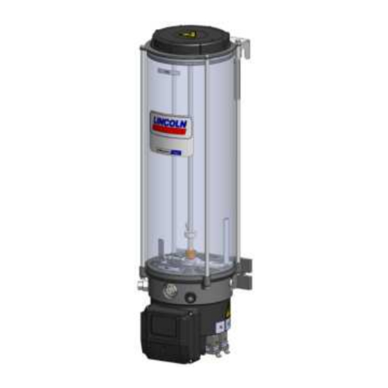
Page 21: Overview, Functional Description
3. Overview, functional description 3. Overview, functional description Overview Fig. 1 1 Reservoir The lubricant is stored in the reservoir. De- pending on the pump version there are differ- ent types of reservoirs and reservoir sizes. 1.1 Reservoir venting device It provides air for the reservoir while the pump is operating and supplying lubricant. - Page 22 3. Overview, functional description Overview Fig. 2 4 Pump elements The pump can be operated with up to 3 pump elements, 5 Filler fitting It serves to fill the reservoir via a suitable filler pump with a corresponding connection. 6 Electrical connections They serve for (6.1) signal connection (X4), for (6.2) power supply connection (X2) and for connection of the low-level indication (6.3) in...
- Page 23 3. Overview, functional description Overview Fig. 3 7 ProProtect indication If the LED (7) is green, the ProProtect protec- tion up to 8 kV is available. If the LED (7) is off despite existing operating voltage, only the standard protection level (EN 61000-6-4) is available.
- Page 24 3. Overview, functional description Overview Fig. 4 8 Follower plate (in case of pumps with fol- lower plate) The follower plate (8) rests on the lubricant and presses it down in the direction of the pump elements by spring force. As a result the suction behaviour of the pump improves.
-
Page 25: Functioning Principle Of The Intermittent Low-Level Indication
3. Overview, functional description 3.1 Functioning principle of the intermittent low-level indication The intermittent low-level indication operates free of contact. Its main components are the following: ○ firmly positioned magnetic switch (I) inside of the reservoir bottom ○ flexible guide plate (II) connected to the stirring paddle with a magnet (III) and a control cam (IV) If the reservoir is filled with a lubrication grease suitable for the intermittent low-level indication and the pump is operating, then the guide plate (II) is de- flected by the resistance of the lubrication grease. -
Page 26: Technical Data
4. Technical data 4. Technical data 4.1 Mechanics P623M Admissible operating temperature range of the pump -25 °C to +55 °C The indicated operating temperature range of the pump presupposes the suitability of the lubricant used for the respective actually existing operat- ing temperature. -
Page 27: Nominal Output Volumes
4. Technical data 4.2 Nominal output volumes Pump element Nominal output per pump element and stroke 0.22 cc The stated nominal outputs per stroke refer to NLGI II lubricating greases at an operating temperature of + 20 °C and a backpressure of 100 bar on the pump element. -
Page 28: Useable Reservoir Volume
4. Technical data 4.3 Useable reservoir volume Regarding the reservoir version without follower plate the useable reservoir volume mainly depends on the NLGI consistency class 1, 2, 3) of the lu- bricant to be used and the operating temperature. In case of high consistency and low operating temperature normally more lubricant sticks to the inner surfaces of the reservoir and the pump and is thus no more available for being dispensed. -
Page 29: Limits Of Use Of The Intermittent Low-Level Indication
4. Technical data 4.5 Limits of use of the intermittent low-level indication The following lubricant consistencies have to be complied with in order to ensure the correct functioning of the intermittent low-level indication. Above the stated range of temperature a correct functioning of the intermittent low-level indication cannot be ensured. The inferior temperature ranges require the suitability of the lubricant for the respective temperature range. -
Page 30: Tightening Torques
4. Technical data 4.6 Tightening torques The stated tightening torques must be adhered to. Pump with supporting construction provided by the customer 25 Nm ± 1,0 Nm Pump element with pump housing 40 Nm ± 2.0 Nm Pressure control valve with pump element 08 Nm + 0.8 Nm Housing front cover with pump housing 2.5 Nm + 0.1 Nm... -
Page 31: Electrics
4. Technical data 4.7 Electrics: Input Connection voltage and frequency range 110-240 V AC ± 10%, 50-60 Hz ± 5% | Phase 1 Current consumption typically 0.82 A at 230 V AC Switch-on current limitation < 40 A (cold start @25 °C) <... -
Page 32: Processing Of The Low-Level Signals In Case Of External Controller And Monitoring Of The Pump
4. Technical data 4.8 Processing of the low-level signals in case of external controller and monitoring of the pump To avoid early low-level indication (e.g. caused by air inclusions or wave formation in the lubricant) in case of external controller or monitoring the following conditions have to be fulfilled by programming the external controller accordingly. -
Page 33: Type Identification Code
4. Technical data 4.9 Type identification code Structure of the type identification code The type identification code facilitates identification of P 6 2 3 M X L B O - 1 K 7 - A C - H 1 Example A important equipment features of the product. -
Page 34: Delivery, Returns, And Storage
5.3 Storage 5.4 Storage temperature range ○ In case of parts not primed with lubri- After receipt of the shipment, check the SKF products are subject to the following shipment for damage and completeness storage conditions: cant the admissible storage temperature ○... -
Page 35: Special Storage Conditions For Parts Primed With Lubricant
5. Delivery, returns, and storage 5.5 Special storage conditions for parts 5.5.3 Storage period exceeding 18 Metering device primed with lubricant months • Remove all connection lines and closure screws, if any. To avoid dysfunctions consult the manufac- The conditions mentioned in the following turer before commissioning. -
Page 36: Installation
6. Installation 6. Installation 6.2 Place of installation 6.1 General information ○ Possibly existing visual monitoring de- Protect the product against humidity, dust Only qualified technical personnel may vices, e.g. pressure gauges, MIN/MAX and vibrations and install it in an easily ac- install the products described in these markings or piston detectors, must be cessible position to facilitate other installa-... -
Page 37: Mechanical Connection
6. Installation 6.3 Mechanical connection Minimum assembly dimensions Fig. 5 6.3.1 Minimum assembly dimensions Ensure sufficient space for maintenance or repair work or for assembly of further components of the centralized lubrication system by leaving a free space of at least 100 mm into each direction in addition to the stated dimensions. -
Page 38: Installation Bores
6. Installation 6.3.2 Installation bores Mounting bores in mm Installation bores Fig. 6 Pumps with 4 l and 8 l reservoirs: 10 l 15 l 20 l Are fastened at the two lower mounting points (A). Pumps with 10 l, 15 l and 20 l reservoirs: 177.5 177,5 177,5... -
Page 39: Electrical Connection
6. Installation Electrical connection, Fig. 7 6.4 Electrical connection WARNING Electric shock Make sure to disconnect the product from the power supply before carrying out any works on electrical components. Connect the cables in such way that no mechanical forces are transferred to the product. -
Page 40: Lubrication Line Connection
6. Installation 6.5 Lubrication line connection ○ The lubricant flow should not be impeded Observe the following installation instruc- CAUTION tions for safe and smooth operation. by the installation of sharp elbows, angle ○ Use clean components and primed lubri- valves, gaskets protruding to the inside, Risk of falling cation lines only. -
Page 41: Filling Via Filler Fitting
6. Installation 6.5.1 Filling via filler fitting Filling via filler fitting Fig. 8 • Place filling connection of the filler pump onto filler fitting R1/4 (5). • Switch on filler pump and fill reservoir with lubricant until shortly below the MAX marking. -
Page 42: Filling Via The Reservoir Lid In Case Of Pumps Without Follower Plate
6. Installation 6.5.2 Filling via the reservoir lid in case Filling via the reservoir lid Fig. 9 of pumps without follower plate WARNING Crushing hazard on the rotating stirring paddle. Fill- ing via the reservoir lid is allowed only after disconnecting the pump from the power supply by remov- ing it from the connection (6.2). -
Page 43: Initial Start-Up
7. Initial start-up 7. Initial start-up In order to warrant safety and function, a person assigned by the operator must carry out the following inspections. Remedy detected de- fects before the initial start-up. Deficiencies may be remedied by an authorized and qualified specialist only. Start-up check list 7.1 Inspections prior to initial start-up Electrical connection carried out correctly... -
Page 44: Operation
8. Operation 8. Operation SKF products operate automatically to the greatest possible extent. Basically, activities during standard opera- tion are limited to the control of the filling level and the timely refilling of lubricant as well as the outside cleaning of the product in case of contamination. -
Page 45: Cleaning
Thoroughly remove residues • Mark and secure wet areas. To do so, contact the SKF Customer Service. of cleaning agents from the • Keep unauthorized persons away. product and rinse off with clear water. -
Page 46: Repairs
12. Repairs Repairs 10.1 Replace pump element and pressure Replace pump element Fig. 10 WARNING control valve Risk of injury The characteristics of the new Before carrying out any repair pump element must correspond work, take at least the following to the characteristics of the safety measures: pump element to be replaced... -
Page 47: Replace Power Supply Board
12. Repairs 10.2 Replace power supply board Remove housing front cover Fig. 11 To replace the power supply board proceed Power supply board Fig. 12 as follows: • Check the new power supply board for accordance with the documentation and the intended purpose. - Page 48 12. Repairs • Place new power supply board in the lat- Power supply board mounted correctly Fig. 15 Removed power supply board Fig. 13 eral guide rails (14.1) and push it into the housing until you notice resistance. 14.1 14.1 •...
-
Page 49: Tests After Replacement Of The Power Supply Board
12. Repairs 10.3 Tests after replacement of the power 10.3.3 Electrical functionality test 10.3.2 Electrical safety test supply board The electrical function test must be carried Use measuring equipment following out immediately after the repair following EN 61557 for the mentioned electrical After replacement of the power supply the protection class of the electrical appara- tests. -
Page 50: Shutdown And Disposal
13. Shutdown and disposal Shutdown and disposal 11.1 Temporary shutdown 11.3 Disposal Temporarily shut the system down by: Countries within the European Union ○ Switching off the superior machine Disposal should be avoided or minimized ○ Disconnecting the product from the Dispose of or recycle electrical wherever possible. -
Page 51: Spare Parts
14. Spare parts Spare parts The spare parts assemblies may be used exclusively for replacement of identical defective parts. Modifications with spare parts on existing products are not allowed. Fig. 16 12.1 Housing front cover, assy. Designation Qty. Part number Consisting of: 545-60167-1 1 x housing front cover... -
Page 52: Pressure Control Valve
14. Spare parts Fig. 18 12.3 Pressure control valve Designation Qty. Part number Pressure control valve SVET-350-G 1/4A-D6 624-29056-1 Pressure control valve SVET-350-G 1/4A-D8 624-29054-1 Fig. 19 12.4 Power supply board Designation Qty. Part number Consisting of: 545-60171-1 1 x power supply board 1 x profile seal 4 x screw with washer 951-171-013... -
Page 53: Electrical Connections
15. Electrical connections / wiring diagrams Electrical connections 13.1 Cable colours following IEC 60757 Abbreviation Colour Abbreviation Colour Abbreviation Colour Abbreviation Colour black green white pink brown yellow orange turquoise blue violet 13.3 Assignment of the circuit diagrams to the pump type 13.2 Wire allocation of the connectors identification code Assignment of the circuit diagrams to a certain pump is done via... -
Page 54: Connection Diagram P623M-Ac-H1
15. Electrical connections / wiring diagrams 13.4 Connection diagram P623M-AC-H1 Connection diagram P623M-AC-H1 Fig. 20 Valid for type identification codes with the following characteristics P 6 2 3 M - A C - H 1 P 6 2 3 M X L B O - A C - H 1 LL-Extern M12x1... -
Page 55: Connection Diagram P623M-Ac-H1.H2
15. Electrical connections / wiring diagrams 13.5 Connection diagram P623M-AC-H1.H2 Connection diagram for P623M-AC-H1.H2 Fig. 21 Valid for type identification codes with the following characteristics P 6 2 3 M - A C - H 1 .H 2 P 6 2 3 M X L B 0 - A C - H 1 .H 2 H18-GNYE-370mm-AWG18 H4.1-BN-AWG18... -
Page 56: Connection Diagram P623M-Ac-H1.H3
15. Electrical connections / wiring diagrams 13.6 Connection diagram P623M-AC-H1.H3 Connection diagram P623M-AC-H1.H3 Fig. 22 Valid for type identification codes with the following characteristics P 6 2 3 M - A C - H 1 .H 3 P 6 2 3 M X L B O - A C - H 1 .H 3 951-171-013 - 56 -... - Page 57 Notes...
- Page 58 SKF Lubrication Systems Germany GmbH Walldorf Facilities Heinrich-Hertz-Str. 2-8 DE - 69190 Walldorf Phone: +49 (0) 6227 33-0 Fax: +49 (0) 6227 33-259 e-mail: Lubrication-germany@skf.com www.skf.com/lubrication 951-171-013-EN Version 02 2020/03/26...
Need help?
Do you have a question about the P623M Series and is the answer not in the manual?
Questions and answers