Table of Contents
Advertisement
Quick Links
Advertisement
Table of Contents

Subscribe to Our Youtube Channel
Related Manuals for Pepperl+Fuchs PS1000-D2-24.40.RM


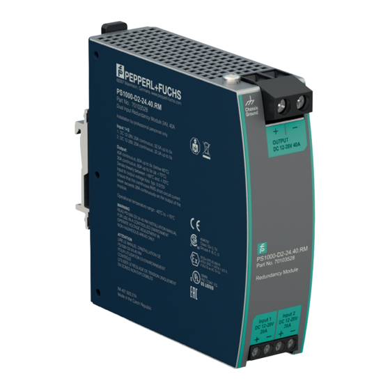
Summary of Contents for Pepperl+Fuchs PS1000-D2-24.40.RM
- Page 1 PS1000-D2-24.40.RM Redundancy Module Technical Information ISO9001...
- Page 2 Phone: +49 621 776 - 0 E-mail: info@de.pepperl-fuchs.com North American Headquarters Pepperl+Fuchs Inc. 1600 Enterprise Parkway Twinsburg, Ohio 44087 Phone: +1 330 425-3555 E-mail: sales@us.pepperl-fuchs.com Asia Headquarters Pepperl+Fuchs Pte. Ltd. P+F Building 18 Ayer Rajah Crescent Singapore 139942 Phone: +65 6779-9091 E-mail: sales@sg.pepperl-fuchs.com https://www.pepperl-fuchs.com...
-
Page 3: Table Of Contents
Power Supply PS1000-D2-24.40.RM Contents Introduction ............5 Terminology and Abbreviations. - Page 4 Power Supply PS1000-D2-24.40.RM Contents...
-
Page 5: Introduction
Power Supply PS1000-D2-24.40.RM Introduction Introduction The information given in this document is correct to the best of our knowledge and experience at the time of publication. If not expressly agreed otherwise, this information does not represent a warranty in the legal sense of the word. As the state of our knowledge and experience is constantly changing, the information in this data sheet is subject to revision. -
Page 6: Terminology And Abbreviations
Power Supply PS1000-D2-24.40.RM Terminology and Abbreviations Terminology and Abbreviations PE and symbol PE is the abbreviation for Protective Earth and has the same meaning as the symbol Earth, Ground This document uses the term earth which is the same as the U.S. term ground. - Page 7 Power Supply PS1000-D2-24.40.RM Terminology and Abbreviations N+1 Redundancy Use of three or more identical power supplies in parallel to provide continued operation following most failures in a single power supply. All power supply outputs should be isolated from each other by utilizing diodes or other switching arrangements.
-
Page 8: Intended Use
Power Supply PS1000-D2-24.40.RM Intended Use Intended Use This device is designed for installation in an enclosure and is intended for commercial use, such as in industrial control, office, communication and instrumentation equipment. Do not use this device in equipment where malfunction may cause severe personal injury or threaten human life. -
Page 9: Installation Instructions
Power Supply PS1000-D2-24.40.RM Installation Instructions Installation Instructions Warning! Risk of electrical shock, fire, personal injury or death. • Turn power off before working on the device and protect against inadvertent re-powering. • Do not open, modify or repair the device. - Page 10 Power Supply PS1000-D2-24.40.RM Installation Instructions A PE (ground) connection is not required. However, connecting the chassis ground terminal to ground can be beneficial to gain a high EMI immunity. The device is designed for convection cooling and does not require an external fan.
-
Page 11: Input And Output Characteristics
Power Supply PS1000-D2-24.40.RM Input and Output Characteristics Input and Output Characteristics Number of inputs Suitable power supplies Use only power supplies which are featured with the Hiccup overload behaviour Number of outputs Input voltage nom. DC 12-28V ±30% The input circuitry must meet the SELV requirements stipulated by IEC/EN/UL 60950-1. -
Page 12: Power Losses
Power Supply PS1000-D2-24.40.RM Power Losses Power Losses DC 12V DC 24V Power losses typ. 1.6W 1.7W input: 2x10A typ. 5.8W 5.9W input: 2x20A typ. 2.3W 2.4W input: 1x20A, (only one input is connected to input voltage) Standby power losses typ. -
Page 13: Lifetime Expectancy And Mtbf
Power Supply PS1000-D2-24.40.RM Lifetime Expectancy and MTBF Lifetime Expectancy and MTBF The redundancy module has two input channels which are completely independent from each other. Each control circuit, auxiliary voltage source, or other circuitry in the module are designed separately for each input. The dual input redundancy module can be considered as two single redundancy modules combined together in one housing. -
Page 14: Terminals And Wiring
Power Supply PS1000-D2-24.40.RM Terminals and Wiring Terminals and Wiring Input Output Type Screw termination Screw termination IP20 Finger safe construction. IP20 Finger safe construction. Suitable for field installation. Suitable for field installation. Solid wire 0.5-6mm 0.5-16mm Stranded wire 0.5-4mm 0.5-10mm... -
Page 15: Functional Diagram
Power Supply PS1000-D2-24.40.RM Functional Diagram Functional Diagram control Input 1 Output C hassis Ground Input 2 control Figure 9.1 Functional diagram... -
Page 16: Front Side And User Elements
Power Supply PS1000-D2-24.40.RM Front Side and User Elements Front Side and User Elements Output terminals (screw terminals) Chassis-ground terminal To be connected on the top side Chassis Ground of the housing with a ring-type terminal (ring cable lug) which is suitable for a M4... -
Page 17: Emc
Power Supply PS1000-D2-24.40.RM The redundancy module is suitable for applications in industrial environment as well as in residential, commercial and light industry environment without any restrictions. A detailed EMC report is available on request. According to generic standards: EN 61000-6-1 and EN 61000-6-2... -
Page 18: Environment
Power Supply PS1000-D2-24.40.RM Environment Environment Operational temperature -40°C to +70°C (-40°F to 158°F) Storage temperature -40 to +85°C (-40°F to 185°F) for storage and transportation Output de-rating 1A/°C 60-70°C (140°F to 158°F) Humidity 5 to 95% r.H. IEC 60068-2-30 Vibration sinusoidal 2-17.8Hz: ±1.6mm;... -
Page 19: Protection Features
Power Supply PS1000-D2-24.40.RM Protection Features Protection Features Output over-current protection not included Reverse input polarity protection included unit does not start when input voltage is reversed Degree of protection IP 20 EN/IEC 60529 Penetration protection > 3.6mm e.g. screws, small parts... -
Page 20: Safety Features
Power Supply PS1000-D2-24.40.RM Safety Features Safety Features Input / output separation no galvanic separation Mosfet between input and output Class of protection PE (Protective Earth) or chassis connection not required PE resistance < 0.1Ohm between housing and chassis-ground terminal... -
Page 21: Dielectric Strength
Power Supply PS1000-D2-24.40.RM Dielectric Strength Dielectric Strength The input and output voltages have the same reference, are floating and have no ohmic connection to ground. Type and factory tests are conducted by the manufacturer. Field tests may be conducted in the field using the appropriate test equipment which applies the voltage with a slow ramp (2s up and 2s down). -
Page 22: Approvals And Fulfilled Standards
Power Supply PS1000-D2-24.40.RM Approvals And Fulfilled Standards Approvals And Fulfilled Standards UL 61010 UL Certificate Listed equipment for category NMTR - UL 61010-2-201 Electrical Equipment for Measurement, Control and Laboratory Use - Particular requirements for control equipment Applicable for US and Canada... -
Page 23: Regulatory Compliance
Power Supply PS1000-D2-24.40.RM Regulatory Compliance Regulatory Compliance EU Declaration of The CE mark indicates conformance with the European Conformity • ATEX directive • EMC directive • Low-voltage directive (LVD) • RoHS directive WEEE Directive Manufacturer's Statement EU-Regulation on Waste Electrical and Electronic Equipment Registered in Germany as business to business (B2B) products. -
Page 24: Physical Dimensions And Weight
Power Supply PS1000-D2-24.40.RM Physical Dimensions and Weight Physical Dimensions and Weight Width 36mm, 1.42 inch Height 124mm, 4.88 inch Depth 127mm, 5.0 inch The DIN mounting rail height must be added to the unit depth to calculate the total required installation depth. -
Page 25: Application Notes
Power Supply PS1000-D2-24.40.RM Application Notes Application Notes 19.1 Recommendations for Redundancy Recommendations for the configuration of redundant power systems: • Use separate input fuses for each power supply. • Use three-phase power supplies to gain functional safety if one phase fails. - Page 26 Power Supply PS1000-D2-24.40.RM Application Notes 19.4 1+1 Redundancy up to 20A 1+1 Redundancy up to 20A requires two 20A power supplies and one redundancy module. Load F ailure Monitor Output DC -OK DC -OK PS1000-D2- 24.40.RM R edundancy P ower...
- Page 27 Power Supply PS1000-D2-24.40.RM Application Notes 19.6 Mounting Orientations Mounting orientations other than input terminals on the bottom and output terminals on the top require a reduction in continuous output power or a limitation in the maximum allowed ambient temperature. The amount of reduction influences the lifetime expectancy of the power supply.
- Page 28 Power Supply PS1000-D2-24.40.RM Application Notes Output C urrent Ambient Temperature 60°C Figure 19.8 Mounting orientation E (horizontal ccw)
- Page 29 Power Supply PS1000-D2-24.40.RM Notes...
- Page 30 Pepperl+Fuchs Quality Download our latest policy here: www.pepperl-fuchs.com/quality www.pepperl-fuchs.com © Pepperl+Fuchs · Subject to modifications Printed in Germany DOCT-7829...
Need help?
Do you have a question about the PS1000-D2-24.40.RM and is the answer not in the manual?
Questions and answers