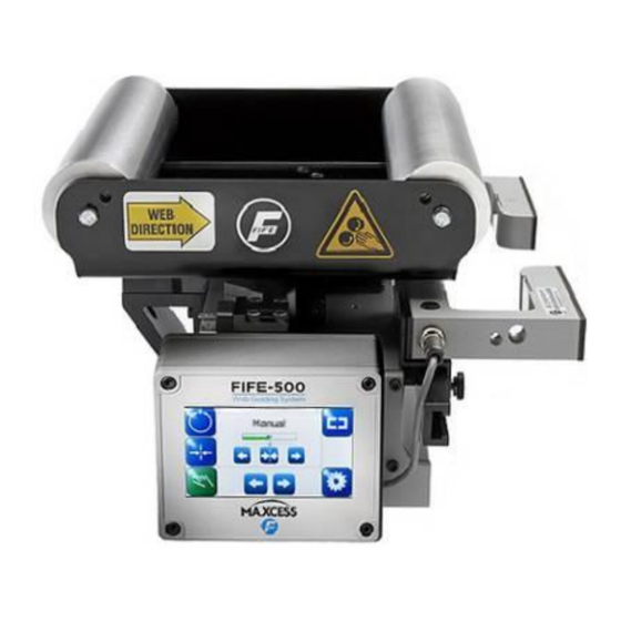
Maxcess FIFE-500 Quick Start Setup
Hide thumbs
Also See for FIFE-500:
- Quick start manual (16 pages) ,
- Installation and service manual (32 pages) ,
- User manual (80 pages)

Subscribe to Our Youtube Channel
Related Manuals for Maxcess FIFE-500


Summary of Contents for Maxcess FIFE-500
- Page 1 FIFE GUIDING SOLUTIONS FIFE-500 / FIFE-500-XL Quick Start Setup Manual For Narrow and Medium Web Guiding Systems MI 2-268 1 A...
-
Page 2: Table Of Contents
Display definitions ....................2-1 Button functions and definitions ................2-3 Status bar definitions ................... 2-5 OPERATION System setup ......................3-1 Auto setup configuration ..................3-3 Optional manual configuration ................3-5 Changing the guidepoint ..................3-6 www.maxcessintl.com FIFE-500 / FIFE-500-XL MI 2-268 1 A... -
Page 3: Introduction
General The instructions contained in this Quick Start Setup Manual are written to support operation of the FIFE-500 and FIFE-500-XL information Web Guiding Systems. The FIFE-500 model number used throughout this document refers to both the FIFE-500 and the FIFE-500-XL, unless otherwise noted. -
Page 4: Features
FEATURES Display definitions The FIFE-500 uses a QVGA Touchscreen for Operator command inputs and status displays. This Control Panel is divided into 5 sections of information for which a brief description is listed below. Refer to Figure 1 for the button locations in the standard horizontal Control Panel. Also refer to your Web Guiding System User Manual for complete display definitions. - Page 5 5. The horizontal section along the bottom contains the Sensor Selection and Setup buttons. The Sensor Select button displays the symbol of the Sensor Mode currently selected. Figure 2 FIFE-500 CONTROL PANEL (90° AND 270° ROTATION) www.maxcessintl.com FIFE-500 / FIFE-500-XL...
-
Page 6: Button Functions And Definitions
FEATURES Button functions and definitions The table below gives the name along with an operational function description of each button displayed on the FIFE-500 Web Guiding System. AUTOMATIC This button initiates the Automatic mode. Correction is applied to the web by moving the guide in response to the output of the sensor(s) that have been selected. - Page 7 ACCEPT This button is used to save a changed value and return to the previous screen. REJECT This button is used to discard a changed value and return to the previous screen. www.maxcessintl.com FIFE-500 / FIFE-500-XL MI 2-268 1 A...
-
Page 8: Status Bar Definitions
FEATURES Status bar definitions The status bar located horizontally across the top of the FIFE-500 Web Guide Operator Level screen remains visible at all times. The number on the left side of the status bar contains the numerical address of the connected motor controller. The number on the right side of the status bar indicates a hierarchical screen number. - Page 9 This icon appears when there is no motor type configured. COMMUNICATION FAULT This icon appears when a problem is detected with the communication signals. This can be caused by hardware or an addressing conflict in a networked system. www.maxcessintl.com FIFE-500 / FIFE-500-XL MI 2-268 1 A...
- Page 10 This icon appears when a problem is detected with the encoder signals from the motor. MOTOR HALL STATE FAULT This icon appears when a problem is detected with the motor magnetic field sensor state transitions. www.maxcessintl.com FIFE-500 / FIFE-500-XL MI 2-268 1 A...
-
Page 11: Operation
OPERATION System setup Setup screens Figure 3 FIFE-500 CONTROL PANEL LEVEL 1 SETUP SCREEN Figure 4 FIFE-500 CONTROL PANEL SENSOR CALIBRATION SCREEN 1. Connect +24 VDC Power to the input receptacle, located on the top side of the Base Assembly. Refer to your Installation Instructions, which are supplied with each system. - Page 12 Press the BACK or HOME button to return to the Operator Level screen. In simulation, these buttons are not available. Once this procedure has been performed once for each sensor, it does not need to be repeated, unless the web/strip opacity has changed. www.maxcessintl.com FIFE-500 / FIFE-500-XL MI 2-268 1 A...
-
Page 13: Auto Setup Configuration
Auto setup configuration NOTE: If Manual Configuration is desired, go to page 3-5. Figure 5 FIFE-500 CONTROL PANEL AUTOSETUP SCREEN 1. Place the web/strip in the proper position and then position the sensor(s) to align the center of the sensor(s) bandwidth with the edge of the web/strip to be guided. - Page 14 Press the Autosetup button to start. The guide will move a short distance and indicate the result as shown in Figure 6 below. Figure 6 FIFE-500 CONTROL PANEL SUCCESSFUL AUTOSETUP COMPLETION Press the ACCEPT button to save the setting.
-
Page 15: Optional Manual Configuration
OPERATION Optional manual configuration Figure 7 FIFE-500 CONTROL PANEL SYSTEM GAIN SETUP SCREEN Setting the gain 1. Press the SETUP button to enter the Setup menus. 2. Press the GAIN icon to enter the Gain menu. 3. Use the + and - ARROW buttons, or use the slider control to adjust the Gain to the desired level. -
Page 16: Changing The Guidepoint
OPERATION Optional manual configuration Figure 8 FIFE-500 CONTROL PANEL GUIDEPOINT SETUP SCREENS Changing the guidepoint while in automatic or manual mode The arrow controls shift the Guidepoint within the active sensor bandwidth. Press the right arrow button move the Guidepoint toward the right sensor.
Need help?
Do you have a question about the FIFE-500 and is the answer not in the manual?
Questions and answers