Table of Contents
Advertisement
Quick Links
MANUFACTURED BY:
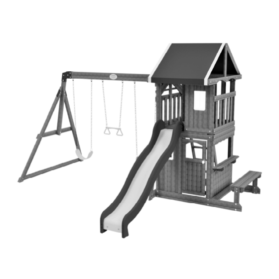
Wooden Swing Set
Backyard Discovery
3305 Airport Drive
Pittsburg, KS 66762
Model # 65114E
Owner's Manual & Assembly Instructions
800-856-4445
WARNING: FOR DOMESTIC USE ONLY.
average 2 person assembly time
assembly time may vary based on skill level
For the most up to date assembly manual,
to register your set, or to order replacement parts please visit
www.backyarddiscovery.com
SAVE THIS ASSEMBLY MANUAL FOR FUTURE REFERENCE IN THE EVENT THAT
YOU NEED TO ORDER REPLACEMENT PARTS.
Made in China | INS-65114E-OAKMONT SWING SET-ENG 06/10/20
Advertisement
Table of Contents

Related Manuals for Backyard Discovery Oakmont 65114E


Summary of Contents for Backyard Discovery Oakmont 65114E
- Page 1 MANUFACTURED BY: Wooden Swing Set Backyard Discovery 3305 Airport Drive Pittsburg, KS 66762 Model # 65114E Owner's Manual & Assembly Instructions 800-856-4445 WARNING: FOR DOMESTIC USE ONLY. average 2 person assembly time assembly time may vary based on skill level...
- Page 2 INSTALLATION SERVICES AVAILABLE! Need a helping hand? *Installation services are only available to U.S. customers. We do the heavy lifting, so you don’t have to! Visit www.goconfigure.com for more info! *Installation services are only available to U.S. customers.
- Page 3 Owner’s Manual Play Set MISSING A PART? CALL US BEFORE GOING BACK TO THE STORE Please have the following information ready when you make your call: y fi...
- Page 4 Owner’s Manual Play Set Please read entire booklet completely before beginning the assembly process Please retain these instructions and your receipt for future reference. Keep them in a safe place where you can refer to them as needed. In order to provide you with the most effi cient service, it is required that you provide us with the part numbers when ordering parts. For Your Records: lease take time and fi Tracking Number Reference Label...
- Page 5 Owner’s Manual Play Set Operating Instructions and Safety Warnings WARNING: BURN HAZARD NOTE: Your Children’s Safety Is Our #1 Concern! MUST NOT LOOK • DO NOT • DRESS CHILDREN APPROPRIATELY. or specifi ell-fi ed fl • DO NOT NEVER or the specifi REQUIRED.
- Page 6 Owner’s Manual Play Set Positioning Your Playcenter Suggested Playground Surfacing e in a fl o not install loose fi...
- Page 7 Owner’s Manual Play Set APPENDIX A The following information is from the United States Consumer Product Safety Commission’s Information Sheet for playground surfacing material; also see the following website for additional information: www.cpsc.gov specifi Specifi specifi Specifi diff...
- Page 8 Owner’s Manual Play Set Instructions for Proper Maintenance IT IS IMPORTANT TO CHECK AND TIGHTEN ALL HARDWARE AT THE BEGINNING AND DURING THE SEASON AS THEY MAY LOOSEN DUE TO WOOD EXPANSION AND CONTRACTION. At the beginning of each play season Additional Maintenance ake and check depth of loose fi Twice a month during play season...
- Page 9 Owner’s Manual Play Set Instructions for Proper Maintenance Your Backyard Discovery structure is designed and constructed of quality materials. As with all outdoor products it will weather and wear. To maximize the enjoyment, safety and life of your structure it is important that you properly maintain it.
- Page 10 Owner’s Manual Play Set Assembly Tips Protrusion Hazard Incorrect Correct Proper Hardware Assembly Bolt and T-Nut Assembly Bolt and Barrel Nut Assembly Lag Assembly...
- Page 11 Owner’s Manual Play Set Assembly Tips ASSEMBLY TIP: Keep and eye out for these boxes which will contain helpful pictures and information making the assembly process as quick and painless as possible. Sorting Wood Sorting Hardware NUT BARREL SCREW T-NUT WASHER FLAT BOLT HEX BOLT...
- Page 12 Owner's Manual...
- Page 13 Owner's Manual Place the set on level ground, not less than 6'-7" [2 m] from any structure or obstruction such as a fence, garage, house, overhanging branches, laundry lines, or electrical wires. While assembling unit, take time before and after each phase to make sure fort is level. If fort is not level, assembly will be difficult and improper assembly may result.
- Page 14 Owner's Manual FRONT LEFT UPRIGHT - W4L14655 1 3/8"x3 3/8"x81 3/4" (36x86x2076) (x1) FRONT RIGHT UPRIGHT - W4L14656 1 3/8"x3 3/8"x81 3/4" (36x86x2076) (x1) BACK LEFT UPRIGHT - W4L14657 1 3/8"x3 3/8"x81 3/4" (36x86x2076) (x1) BACK RIGHT UPRIGHT - W2A02867 1 3/8"x3 3/8"x81 3/4"...
- Page 15 Owner's Manual DOOR STOP - W4L14671 1"x2 3/8"x2" (24x60x50) (x1) GROUND BOARD - W4L14672 5/8"x5 1/4"x59" (16x134x1499) (x1) GROUND BOARD - W4L14673 5/8"x5 1/4"x60 1/2" (16x134x1538) (x2) GROUND BOARD - W4L14674 GROUND BOARD - W4L14675 (x1) 5/8"x3 3/8"x47 1/2" (16x86x1205) 5/8"x5 1/4"x40 1/8"...
- Page 16 Owner's Manual WALL BOARD - W4L14692 SERVING HEADER - W4L14693 5/8"x3 3/8"x30" (16x86x762) 5/8"x3 3/8"x40 1/8" (16x86x1018) (x2) (x1) WINDOW WALL BOARD - W4L14694 WALL RAIL - W4L14695 (x2) 5/8"x3 3/8"x25" (16x86x634) 5/8"x3 3/8"x19 1/4" (16x86x490) (x1) PICKET - W4L14696 WALL RAIL - W4L14697 5/8"x3 3/8"x17 3/4"...
- Page 17 Owner's Manual SB74 SWING BEAM EXTENDED - W4L14650 2"x5 1/4"x89 1/2" (50x134x2274) (x1) SUPPORT RAIL - W4L14711 1"x1 3/8"x20" (24x34x507) (x2) SWING BEAM SUPPORT - W4L14654 2"x3 3/8"x50 3/8" (50x86x1280) (x1) FLOOR PANEL - W2A02865 1 1/4"x19 1/8"x41 7/8" (36x485x1064) (x2) DOOR PANEL - W2A02866 1 1/2"x16 3/8"x36 3/8"...
-
Page 18: Table Of Contents
Owner's Manual H100166 BOLT WH H100006 NUT BARREL WH (x4) (x3) 5/16x4-1/4 5/16x1 1/2 H100019 BOLT WH H100005 NUT BARREL WH (x2) 5/16x3 3/4 (x31) 5/16x7/8 H100016 BOLT WH H100004 NUT BARREL WH (x2) (x13) 5/16x3 5/16 x 5/8 H100047 BOLT HEX H100014 BOLT WH... - Page 19 Owner's Manual H100138 WASHER LOCK EXT H100090 SCREW PFH (x8) 6x15 (x33) 8x2 1/2" H100111 SCREW PFH H100137 BOLT WH (x26) (x2) 1/4x1 H100030 WASHER LOCK EXT H100089 SCREW PFH (x95) 8x19 (x13) 8x1 3/4 H101027 BOLT WH H100086 (x2) SCREW PFH 1/4x1-3/4 (x95)
- Page 20 Owner's Manual...
- Page 21 Owner's Manual A100069 QUICK LINK (x6) A6P00303 HAND GRIP YELLOW PLASTIC (x2) A100177 CHAIN GREEN 31" (x2) A100068 CHAIN GREEN 51.25" (x4) A100171 SWING SEAT YELLOW 22" (x2) A4M01169 A-FRAME BRACKET (x1) A100325 SWING BEAM EXTENSION BRACKET-LEFT (x1) A100326 A100140 SWING BEAM EXTENSION BRACKET-RIGHT L BRACKET 66x66x127 (x1)
- Page 22 Owner's Manual A100314 A6P00034 "A" REVISION TAG TRAPEZE YELLOW (x1) (x1) A6P00019 WINDOW (FLAT PACK) (x2) A6P00033 SLIDE BED 8' YELLOW (x1) A4M01046 L BRACKET 2.5x38x55x55 (x8) A6P00035 TARP .32x1014x2195 (x1) A6P00020 LATCHING KNOB KIT (x1) A100164 BYD ID TAG (LARGE) AGES 3-10 (x1)
- Page 23 LADDER ASSEMBLY M104 LADDER RUNG - W4L14649 LEFT UPRIGHT - W4L14645 H100111 SCREW PFH 1"x3 3/8"x17 1/8" (24x86x434) (x1) 1"x3 3/8"x50 3/4" (24x86x1290) (x4) (x8)
- Page 24 LADDER ASSEMBLY RIGHT UPRIGHT - W4L14646 H100111 SCREW PFH 1"x3 3/8"x50 3/4" (24x86x1290) (x8) (x1)
- Page 25 LADDER ASSEMBLY H100086 M103 SCREW PFH REAR SUPPORT - W4L14648 (x4) 5/8"x3 3/8"x18 1/4" (16x86x462) 8x1 1/2 (x1)
- Page 26 LADDER ASSEMBLY H100089 SCREW PFH ATTACHMENT BOARD - W4L14647 (x4) 8x1 3/4 1"x3 3/8"x18 1/4" (24x86x462) (x1) FLUSH...
- Page 27 SWING BEAM ASSEMBLY SWING BEAM SWING BEAM A100326 A100325 EXTENSION EXTENSION (x1) (x1) BRACKET-RIGHT BRACKET-LEFT SB74 SWING BEAM EXTENDED - W4L14650 2"x5 1/4"x89 1/2" (50x134x2274) (x1) L BRACKET A100140 (x2) 66x66x127 H100047 BOLT HEX H100105 H100110 WASHER FLAT NUT LOCK (x2) 5/16x2 3/4 (x4)
-
Page 28: H100019 Bolt Wh
SWING BEAM ASSEMBLY SWING BEAM SUPPORT - W4L14654 END SUPPORT - W4L14651 2"x3 3/8"x50 3/8" (50x86x1280) 1 1/2"x3 1/2"x46" (36x86x1168) (x1) (x1) A4M01169 GROUND BOARD - W4L14653 ANGLE BRACE - W4L14652 A-FRAME BRACKET (x1) 1"x3 3/8"x79 1/2" (24x86x2018) 1 3/8"x3 3/8"x81" (36x86x2056) (x1) (x2) H100019... -
Page 29: Nut Barrel Wh 5/16X1
SWING BEAM ASSEMBLY (x1) SWING BEAM END SUBASSEMBLY (x1) SWING BEAM SUBASSEMBLY H100014 BOLT WH H100011 H100005 NUT BARREL WH BOLT WH H100006 NUT BARREL WH (x1) 5/16x2 1/2 (x2) (x2) 5/16x1 3/4 5/16x7/8 (x1) 5/16x1 1/2 SWING BEAM SUBASSEMBLY SWING BEAM END SUBASSEMBLY... -
Page 30: Nut Lock
SWING BEAM ASSEMBLY H100099 SWING HANGER (x6) 5/16x9 1/2 H100103 WASHER SAFETY H100105 WASHER FLAT H100110 NUT LOCK (x6) (x6) (x6) 17x30 8x27 5/16... - Page 31 SLIDE ASSEMBLY SLIDE SUPPORT BOARD - W4L04711 A6P00033 SLIDE BED 8' YELLOW (x1) 5/8"x3 3/8"x14 1/4" (16x86x362) (x1) H100115 BOLT WH H100074 T-NUT (x2) (x2) 5/16x1/2 5/16 PLACE 'M77' SLIDE BRACE BOARD 1/4" FROM THE BOTTOM EDGE OF THE SLIDE BED. USING THE BOARD AS A TEMPLATE, MARK WHERE THE PILOT HOLES WILL BE DRILLED.
- Page 32 SLIDE ASSEMBLY A100055 SLIDE RAIL 8' GREEN LEFT (x1) CENTER SLIDE BRACE - W4L04712 5/8"x3 3/8"x14 1/4" (16x86x362) (x2) A100054 SLIDE RAIL 8' GREEN RIGHT (x1) H100090 SCREW PFH (x24) 8x2 1/2" USING A 1/8" DRILL BIT, DRILL PILOT HOLES IN EACH INDENTATION ALONG EACH SIDE RAIL. THERE SHOULD BE 12 INDENTIONS ON EACH RAIL.
-
Page 33: T-Nut
FORT ASSEMBLY LEFT ROOF RAIL - W4L14660 BACK LEFT UPRIGHT - W4L14657 1"x3 3/8"x60" (24x86x1524) (x1) 1 3/8"x3 3/8"x81 3/4" (36x86x2076) (x1) FLOOR SUPPORT - W4L14669 FRONT LEFT UPRIGHT - W4L14655 1"x3 3/8"x40 1/8" (24x86x1018) (x1) 1 3/8"x3 3/8"x81 3/4" (36x86x2076) (x1) GROUND BOARD - W4L14674 GROUND BOARD - W4L14672... - Page 34 FORT ASSEMBLY H100008 BOLT WH H100004 NUT BARREL WH BRACE - W4L14690 (x6) 5/16x1 (x6) 5/16 x 5/8 5/8"x3 3/8"x26 5/8" (16x86x676) (x2) H100031 WASHER LOCK H100030 WASHER LOCK (x6) (x6) 12x19 8x19...
- Page 35 FORT ASSEMBLY SWING BEAM RAIL - W4L14664 SAFETY RAIL - W4L14709 WALL BOARD - W4L14703 1"x3 3/8"x40 1/8" (24x86x1018) 5/8"x1 3/8"x40 1/8" (16x34x1018) 5/8"x3 3/8"x40 1/8" (16x86x1018) (x1) (x1) (x1) H100166 BOLT WH H100027 LAG SCREW WH H100086 SCREW PFH (x2) (x2) (x2)
- Page 36 FORT ASSEMBLY FRONT RIGHT UPRIGHT - W4L14656 RIGHT ROOF RAIL - W4L14661 (x1) 1 3/8"x3 3/8"x81 3/4" (36x86x2076) 1"x3 3/8"x60" (24x86x1524) (x1) BACK RIGHT UPRIGHT - W2A02867 FLOOR SUPPORT - W4L14663 1 3/8"x3 3/8"x81 3/4" (36x86x2076) (x1) 1"x3 3/8"x40 1/8" (24x86x1018) (x1) SERVING SHELF SUPPORT - W4L14686 GROUND BOARD - W4L14675...
- Page 37 FORT ASSEMBLY WALL BOARD - W4L14687 5/8"x3 3/8"x40 1/8" (16x86x1018) (x1) H100027 LAG SCREW WH H100030 WASHER LOCK EXT (x4) 5/16x2 (x4) 8x19 SERVING HEADER - W4L14693 5/8"x3 3/8"x40 1/8" (16x86x1018) (x1)
- Page 38 FORT ASSEMBLY FLOOR SUPPORT - W4L14700 GROUND BOARD - W4L14673 5/8"x3 3/8"x40" (16x86x1016) (x1) 5/8"x5 1/4"x60 1/2" (16x134x1538) (x2) FLOOR SUPPORT - W4L14688 ARCHED ROOF BOARD - W4L14681 ARCHED ROOF BOARD - W4L14682 5/8"x3 3/8"x40" (16x86x1016) 5/8"x4 3/8"x40" (16x112x1016) (x1) (x1) 5/8"x4 3/8"x40"...
- Page 39 FORT ASSEMBLY STANDARD ANGLE BRACE - W4L14658 1 3/8"x2 3/8"x13" (36x60x330) (x1) A100314 "A" REVISION TAG FLOOR JOIST - W4L14662 (x1) 1"x3 3/8"x40 1/8" (24x86x1018) (x1) H100090 SCREW PFH H100138 WASHER LOCK EXT (x4) 8x2 1/2" H100649 LAG SCREW WH H100012 BOLT WH (x1)
-
Page 40: (X95) 8X1
FORT ASSEMBLY FLOOR BOARD - W4L14684 H100086 SCREW PFH 5/8"x3 3/8"x41 7/8" (16x86x1064) (x1) (x61) 8x1 1/2 FLOOR PANEL - W2A02865 1 1/4"x19 1/8"x41 7/8" (36x485x1064) (x2) -
Page 41: Screw Pfh
FORT ASSEMBLY WALL BOARD - W4L14679 3/8"x3 3/8"x19 1/2" (11x86x495) (x10) H100085 SCREW PFH (x45) RIGHT WALL BOARD - W4L14678 3/8"x2 3/4"x37 1/2" (11x70x954) (x1) 2 5/8 [67 mm] INSTALL 'K92' WALL MARK BOARD FIRST AGAINST POST. THEN EVENLY SPACE 'K93' WALL BOARDS UP TO THE 2 5/8 MARK. - Page 42 FORT ASSEMBLY LEFT WALL BOARD - W4L14677 H100085 SCREW PFH 3/8"x2 3/4"x37 1/2" (11x70x954) (x1) (x5)
-
Page 43: (X92) 8X1
FORT ASSEMBLY SHELF SUPPORT - W4L14668 H100086 SCREW PFH 1"x3 3/8"x4 1/2" (24x86x114) (x2) (x5) 8x1 1/2 H100090 SCREW PFH (x2) 8x2 1/2" SERVING SHELF - W4L14676 5/8"x5 1/4"x40 1/8" (16x134x1018) (x1) - Page 44 FORT ASSEMBLY WALL BOARD - W4L14706 WINDOW WALL BOARD - W4L14699 5/8"x2 3/8"x41" (16x60x1040) (x1) 5/8"x3 3/8"x6 1/2" (16x86x164) (x2) H100088 SCREW PFH (x20) 8x1 1/8 WINDOW WALL BOARD - W4L14694 WALL BOARD - W4L14685 5/8"x3 3/8"x25" (16x86x634) (x2) 5/8"x3 3/8"x41" (16x86x1040) (x2) 3 3/4 [96 mm]...
-
Page 45: Screw Pwh
FORT ASSEMBLY WINDOW CLEAT - W4L14680 (x1) 3/8"x1 1/8"x9 7/8" (11x30x252) FOLD OUTWARD BOTH A6P00019 WINDOW (FLAT PACK) SIDES AT THIS LOCATION (x1) H100128 SCREW PWH H100070 SCREW PWH (x4) (x4) 8x5/8 8x3/4... - Page 46 FORT ASSEMBLY HINGE BOARD - W4L14705 H100088 SCREW PFH 5/8"x2 3/8"x37 3/4" (16x60x958) (x2) (x8) 8x1 1/8 FLUSH EDGES...
- Page 47 FORT ASSEMBLY WALL RAIL - W4L14695 5/8"x3 3/8"x19 1/4" (16x86x490) (x1) H100012 H100074 T-NUT BOLT WH H100030 WASHER LOCK EXT (x2) (x2) 5/16x2 (x2) 5/16 8x19 WALL RAIL - W4L14697 5/8"x3 3/8"x16 5/8" (16x86x422) (x1)
- Page 48 FORT ASSEMBLY WALL BOARD - W4L14687 5/8"x3 3/8"x40 1/8" (16x86x1018) (x1) H100027 LAG SCREW WH H100030 WASHER LOCK EXT (x4) 5/16x2 (x4) 8x19 WALL BOARD - W4L14701 5/8"x3 3/8"x40 1/8" (16x86x1018) (x1)
- Page 49 FORT ASSEMBLY WALL BOARD - W4L14707 WALL BOARD - W4L14692 5/8"x2 3/8"x30" (16x60x762) (x1) 5/8"x3 3/8"x30" (16x86x762) (x1) WINDOW WALL BOARD - W4L14698 5/8"x3 3/8"x14" (16x86x356) (x2) WALL BOARD - W4L14702 A4M01046 L BRACKET 2.5x38x55x55 (x1) 5/8"x3 3/8"x31 3/4" (16x86x808) (x1) WINDOW WALL BOARD - W4L14699 5/8"x3 3/8"x6 1/2"...
- Page 50 FORT ASSEMBLY WINDOW CLEAT - W4L14680 (x1) 3/8"x1 1/8"x9 7/8" (11x30x252) FOLD OUTWARD BOTH A6P00019 WINDOW (FLAT PACK) SIDES AT THIS LOCATION (x1) H100128 SCREW PWH H100070 SCREW PWH (x4) (x4) 8x5/8 8x3/4...
- Page 51 FORT ASSEMBLY PICKET - W4L14704 PICKET - W4L14696 H100088 SCREW PFH 5/8"x3 3/8"x20 1/8" (16x86x512) 5/8"x3 3/8"x17 3/4" (16x86x452) (x5) (x4) (x36) 8x1 1/8 3 3/8 [86 mm] 10 3/16 [258 mm] 3 3/8 3 3/8 [86 mm] [86 mm] 3 3/8 3 3/8 [86 mm]...
- Page 52 FORT ASSEMBLY HANDLE WALL BOARD - W4L14691 WALL BOARD - W4L14692 5/8"x3 3/8"x31 3/4" (16x86x808) 5/8"x3 3/8"x30" (16x86x762) (x1) (x1) A4M01046 L BRACKET 2.5x38x55x55 (x1) H100008 BOLT WH H100115 BOLT WH H100005 NUT BARREL WH (x1) (x1) 5/16x1 5/16x1/2 (x1) 5/16x7/8 H100088 H100031...
- Page 53 FORT ASSEMBLY END ROOF RAIL - W4L14683 A4M01046 5/8"x3 3/8"x41 7/8" (16x86x1064) (x2) L BRACKET 2.5x38x55x55 (x4) H100115 H100074 H100031 BOLT WH T-NUT WASHER LOCK EXT H100005 NUT BARREL WH (x8) (x4) (x4) 5/16x1/2 5/16 12x19 (x4) 5/16x7/8 INSTALL T-NUTS INTO BOARDS BEFORE BOARD ASSEMBLY.
-
Page 54: H100031 Washer Lock Ext
FORT ASSEMBLY TOP ROOF RAIL - W4L14689 ROOF UPRIGHT - W4L14665 5/8"x3 3/8"x40" (16x86x1016) (x1) 1"x3 3/8"x24" (24x86x610) (x1) A4M01046 L BRACKET 2.5x38x55x55 ROOF UPRIGHT - W4L14670 (x2) 1"x3 3/8"x55 1/4" (24x86x1404) (x1) H100011 H100010 H100115 BOLT WH BOLT WH BOLT WH H100005 NUT BARREL WH... - Page 55 FORT ASSEMBLY SUPPORT RAIL - W4L14711 1"x1 3/8"x20" (24x34x507) (x2) WALL RAIL - W4L14659 1"x5 1/4"x22" (24x134x558) (x2) H100010 H100111 H100030 H100086 H100074 BOLT WH SCREW PFH WASHER LOCK EXT SCREW PFH T-NUT (x2) (x8) (x2) (x4) 8x1 1/2 (x2) 5/16 5/16x1-1/2 8x19...
- Page 56 FORT ASSEMBLY H100128 SCREW PWH (x8) 8x5/8 A6P00035 TARP .32x1014x2195 (x1) 1 9/16 [40 mm] FOLD OVER...
- Page 57 FORT ASSEMBLY H100008 BOLT WH H100005 NUT BARREL WH BENCH UPRIGHT - W4L14666 (x4) 5/16x1 (x4) 5/16x7/8 (x2) 1"x3 3/8"x15" (24x86x380) H100030 H100031 WASHER LOCK EXT WASHER LOCK EXT (x4) 8x19 (x4) 12x19...
- Page 58 FORT ASSEMBLY SEAT SUPPORT - W4L14667 H100011 BOLT WH H100030 WASHER LOCK EXT H100074 T-NUT 1"x3 3/8"x8 1/2" (24x86x216) (x2) (x4) (x4) (x4) 5/16 5/16x1 3/4 8x19 INSTALL T-NUTS INTO BOARDS BEFORE BOARD ASSEMBLY.
- Page 59 FORT ASSEMBLY H100089 SCREW PFH BENCH SEAT - W4L14710 (x8) 8x1 3/4 1"x4 3/8"x40 1/8" (24x112x1018) (x2)
- Page 60 FORT ASSEMBLY H101027 BOLT WH (x2) 1/4x1-3/4 H100138 WASHER LOCK EXT H100072 T-NUT (x4) (x4) 6x15 A6P00303 H100137 BOLT WH HAND GRIP YELLOW PLASTIC (x2) (x2) 1/4x1 INSTALL T-NUTS INTO BOARDS BEFORE BOARD ASSEMBLY.
- Page 61 FORT ASSEMBLY DOOR STOP - W4L14671 H100086 SCREW PFH H100087 SCREW PFH DOOR STOP SUPPORT - W4L14708 (x3) 8x1 1/2 (x2) 8x1 1/4 1"x2 3/8"x2" (24x60x50) (x1) 5/8"x2 3/8"x4 7/8" (16x60x125) (x1) 6 11/16 [170 mm]...
- Page 62 FORT ASSEMBLY H100086 SCREW PFH (x11) 8x1 1/2 DOOR PANEL - W2A02866 1 1/2"x16 3/8"x36 3/8" (38x416x924) (x1) CENTER DOOR TOP TO BOTTOM IN OPENING FLUSH DOOR WITH FRONT SURFACE OF 'N1' BOARDS CENTER DOOR TOP TO BOTTOM IN OPENING...
- Page 63 FORT ASSEMBLY A6P00020 LATCHING KNOB KIT (x1) SCREW - 3/4" SCREW - 1"...
- Page 64 FORT ASSEMBLY H100074 T-NUT H100030 WASHER LOCK H100010 BOLT WH (x2) 5/16 (x2) (x2) 5/16x1-1/2 8x19 LADDER ASSEMBLY (x1) INSTALL T-NUTS INTO BOARDS BEFORE LADDER ASSEMBLY. LADDER ASSEMBLY...
-
Page 65: Washer Split
FORT ASSEMBLY SWING BEAM ASSEMBLY (x1) A100164 BYD ID TAG (LARGE) AGES 3-10 (x1) H100044 BOLT HEX H100105 WASHER FLAT H100095 WASHER SPLIT H100074 T-NUT H100124 SCREW PFH (x4) (x4) (x4) (x4) (x4) 5/16x2 8x27 5/16 5/16 8 x 1/2... - Page 66 FORT ASSEMBLY H100115 BOLT WH H100074 T-NUT (x3) (x3) 5/16x1/2 5/16 9208063 SLIDE ASSEMBLY (x1) 1. DRILL (3) 7/16" DIA HOLES THROUGH SLIDE BED AND DECK AT LOCATIONS SHOWN. 2. INSTALL T-NUTS INTO DECK BOARDS BEFORE INSTALLATION OF SLIDE. 3 7/8 3 7/8 INSTALL SLIDE AGAINST POST AS SHOWN.
-
Page 67: (X4)
FORT ASSEMBLY A100069 A100171 QUICK LINK SWING SEAT YELLOW 22" (x4) (x2) A100068 CHAIN GREEN 51.25" (x4) WHEN HANGING YOUR SWINGS IT IS RECOMMENDED THAT THE TIGHTEN BOTTOM OF THE SWING SEAT, QUICK WHEN SITTING ON IT, IS LOCATED NO LOWER THAN (35 cm) 13 7/8 LINK INCHES FROM THE GROUND. - Page 68 FORT ASSEMBLY A100177 CHAIN GREEN 31" (x2) A6P00034 A100069 TRAPEZE YELLOW QUICK LINK (x1) (x2) TIGHTEN QUICK LINK INSERT CHAIN INTO QUICK LINK...
- Page 69 FORT ASSEMBLY H100222 BOLT WH A100178 H100031 WASHER LOCK EXT AUGER GROUND STAKE (x4) 5/16x3/4 (x6) (x6) 12x19 H100008 BOLT WH H100004 NUT BARREL WH (x2) 5/16x1 (x6) 5/16 x 5/8 TWIST GROUND STAKE INTO THE GROUND WHERE SHOWN. THEN USING GROUND STAKE AS A GUIDE, DRILL A 7/16"...
Need help?
Do you have a question about the Oakmont 65114E and is the answer not in the manual?
Questions and answers