
Subscribe to Our Youtube Channel
Related Manuals for Gasboy Islander PLUS

Summary of Contents for Gasboy Islander PLUS
- Page 1 Wiring MDE - 4811F Islander PLUS and ICR PLUS INSTALLATION MANUAL This document is based on Orpak’s Island controller (OrIC) installation manual P/N 817438050...
- Page 2 SAFETY CONSIDERATIONS Read all warning notes and instructions carefully. They are included to help you installing the Product safely in the highly flammable environment of the fuel station. Disregarding these warning notes and instructions could result in serious injury or property damage. It is the installer responsibility to install, operate and maintain the equipment according to the instructions given in this manual, and to conform to all applicable codes, regulations and safety measures.
- Page 3 WARNING Components substitutions could impair intrinsic safety. Attaching unauthorized components or equipment will void your warranties. CAUTION Do not attempt to make any repair on the printed circuit boards residing in the Product, as this will void all warranties related to this equipment. PROPRIETY NOTICE This document contains propriety and confidential information.
- Page 4 This document is the property of: ORPAK SYSTEMS Ltd. ISRAEL...
-
Page 5: Table Of Contents
Refueling Scenario with Magnetic Cards ..............5 1-4. ISLANDER PLUS STRUCTURE ..................6 1-4.1. Main Components ......................6 1-4.2. Islander PLUS Internal Configuration – Mechanical Pump .......... 9 1-4.3. Islander PLUS Main Components Location ..............11 1-5. AVAILABLE CONFIGURATIONS ................. 16 1-5.1. - Page 6 Cables Routing ....................... 37 2-7. POWER SETUP ......................... 37 2-7.1. General ........................... 37 2-7.2. Islander PLUS for 8 hoses - AC Power Supply Setup ........... 38 2-7.3. Connecting the Power Equipment .................. 40 2-7.4. Grounding........................40 2-8. WIRING THE PERIPHERALS ..................41 2-8.1.
- Page 7 In the Islander PLUS pole ..................49 3-4.4. Mapping ......................... 49 3-5. CONNECTIONS TO ISLANDER PLUS ................50 3-6. INSTALLING THE ISLANDER PLUS PEDESTAL POLE ..........52 3-6.1. General ........................... 52 3-6.2. Installation Procedure Steps ................... 52 3-6.3. Pedestal Site Preliminary Setup Procedures ..............52 3-6.4.
- Page 8 3-10.1. General ........................... 77 3-10.2. Connection to TLG Controller ..................77 3-10.3. Connection to Journal Printer ..................77 3-11. POST-INSTALLATION CHECKLIST ................80 3-12. ISLANDER PLUS SETUP ....................80 SECTION 4 PRINTER 4-1. OVERVIEW ........................81 4-2. DESCRIPTION ........................82 4-3.
- Page 9 4-11. THERMAL PAPER STORAGE ..................94 SECTION 5 MAINTENANCE 5-1. GENERAL .......................... 95 5-2. TROUBLESHOOTING ..................... 95 5-2.1. Islander PLUS Troubleshooting ..................95 5-2.2. OrPT Troubleshooting ....................102 5-2.3. Printer Troubleshooting ....................106 5-2.4. Communication Troubleshooting .................. 108 5-3. CLEANING ........................111 5-3.1.
- Page 10 TABLE OF CONTENTS Paragraph Page INSTALLATION INSTRUCTIONS ..................... 127 Islander PLUS Manual...
- Page 11 Figure 3-16 Islander PLUS – Terminal Block –4 Mechanical Pump - Wiring List Label ....64 Figure 3-17 Islander PLUS – Terminal Block – 8 Mechanical Pump - Wiring List Label ....65 Figure 3-18 Mechanical Pump – Single Dispenser Connections ............. 67...
- Page 12 Figure 3-19 Mechanical Pump – Twin Dispenser Connections ............68 Figure 3-20 Islander PLUS and Mechanical Pump - Terminal Block Detailed Connections ..69 Figure 3-21 Terminal Block and 3-Wire Pulser – Wiring Connections ........... 70 Figure 3-22 Terminal Block and 2-Wire Pulser – Wiring Connections ........... 71 Figure 3-23 Islander PLUS Terminal Block –...
- Page 13 Table 2-3. Islander PLUS, Cables Routing ..................37 Table 3-1. Islander PLUS, Assembly Parts ..................53 Table 3-2. Islander PLUS Terminal Block -4 Mechanical Pump – Connections Definition ... 59 Table 3-3. Islander PLUS for 8 hoses Terminal Block -8 Mechanical Pump – Connections Definition ............................
-
Page 15: General Description
1-1. SCOPE This manual is provided to assist you in installing Islander PLUS / ICR PLUS. The system must be installed as described in this manual to ensure the system reliability and proper operation. This manual includes a general and functional description of the products, their main components, installation requirements and procedures. -
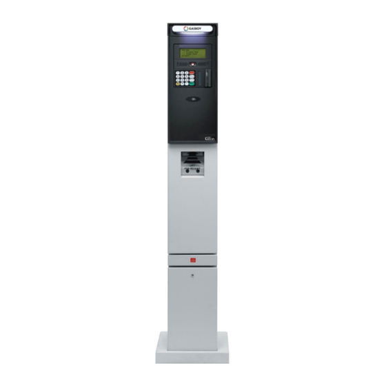
Page 16: Figure 1-1 - Islander Plus / Icr Plus - General View
Figure 1-1 - Islander PLUS / ICR PLUS - General View Islander PLUS Manual... -
Page 17: System Overview
SYSTEM OVERVIEW 1-3.1. Islander PLUS System Islander PLUS is an innovative product that enables refueling in Home Base stations for fleets authorized vehicles or drivers. Islander PLUS electronically locks all dispensers and pumps thereby ensuring that only appropriately authorized vehicles and plants receive the required fuel. The system also ensures accurate recording of each transaction (see Figure 1-2). -
Page 18: 1-3.6. Islander Plus Capabilities For Forecourt Management
• Support of large variety of communication links: cellular, dial-in modem, VPN, satellite, ADSL and more. Figure 1-2 - Islander PLUS in Home Base Station - General Configuration Diagram 1-3.7. System Workflow Example Following are examples of an operational workflow for self-service at the Home Base Station. -
Page 19: 1-3.7.1. Refueling Scenario With Fuelpoint Plus
Payment Panel keyboard, or by scanning a barcode in the Barcode Reader (optional) on the front panel. Once the refueling is completed, the motorist replaces the nozzle to pump. In both options, the motorist may print a transaction ticket from the Islander PLUS printer (optional). -
Page 20: Islander Plus Structure
1-4. ISLANDER PLUS STRUCTURE 1-4.1. Main Components Following is a short description of the Islander PLUS main sub units (see Figure 1-3 and Figure 1-5): Orpak Controller Unit (OrCU) Orpak Controller Unit (OrCU) is a complete forecourt controller with its own embedded operating system. - Page 21 The printer is linked to the central payment terminal that sends to it the transaction data for printout (see Figure 1-7). The thermal printer is installed at the center of the Islander PLUS pedestal door. It includes an integrated paper cutter, paper feeder, paper spool and an "End of paper"...
- Page 22 8-Port CommVerter The 8-Port CommVerter consists of a communication board for all Islander PLUS electronic units and for the peripheral equipment interface. The CommVerter includes two MPI-C cards for interface to the mechanical pumps, an Ethernet Switch, RS/485 ports and one RS/232 port. For electronic pump, a different interface card is installed.
-
Page 23: 1-4.2. Islander Plus Internal Configuration - Mechanical Pump
1-4.2. Islander PLUS Internal Configuration – Mechanical Pump Figure 1-3 shows a general configuration diagram of the Islander PLUS up to four mechanical pumps. Figure 1-3 - Internal Configuration Diagram – 4 Mechanical Pump Islander PLUS Manual... -
Page 24: Figure 1-4 - Internal Configuration Diagram - 8 Mechanical Pumps
Figure 1-4 shows a general configuration diagram of the Islander PLUS for eight mechanical pumps. Figure 1-4 - Internal Configuration Diagram – 8 Mechanical Pumps Islander PLUS Manual... -
Page 25: 1-4.3. Islander Plus Main Components Location
The following Figure 1-5 shows the location of the main components of the Islander PLUS, without the Printer. Figure 1-6 shows the location of the main components of the Islander PLUS for 8 hoses. Figure 1-7 and Figure 1-8 show the location of the Printer within the two configurations, when it is installed. -
Page 26: Figure 1-6 - Internal Components Location -8 Mechanical Pumps
Figure 1-6 - Internal Components Location –8 Mechanical Pumps Islander PLUS Manual... -
Page 27: Figure 1-7 - Islander Plus With Optional Internal Printer (Sectional View)
Figure 1-7 – Islander PLUS with Optional Internal Printer (Sectional View) Islander PLUS Manual... -
Page 28: Figure 1-8 - Islander Plus For 8 Hoses With Optional Internal Printer (Sectional View)
Figure 1-8 – Islander PLUS for 8 hoses with Optional Internal Printer (Sectional View) Islander PLUS Manual... -
Page 30: Available Configurations
ICR PLUS is linked to another Islander PLUS or CFN PLUS in order to connect to the Head Office. In this configuration, the OrCU in the Islander PLUS pedestal is shared by both units. -
Page 31: 1-5.6. Contactless Tags/Cards
Sockets (see Figure 1-9). The key reader is installed behind the printer door cover on the front panel. Figure 1-9 – Islander PLUS with Data Key Reader (Optional) 1-5.6.2. HID Device The pedestal can be supplied with an optional HID card reader for payment with specific cards. -
Page 32: Table 1-1. Islander Plus - Standard Models
Islander PLUS w/Fleetkey for Electric Pumps PA039401000 800938167 800938169 PA039401200 Islander PLUS w/Fleetkey for Mechanical Pumps - 2 hose 800938171 PA039401400 Islander PLUS w/Fleetkey for Mechanical Pumps - 4 hose Islander PLUS w/Fleetkey for Mechanical Pumps - 8 hose PA039401801... -
Page 33: Table 1-2. Pump Card Definition
800938202 PA039501410 hose NOTE Islander PLUS with 8 mechanical dispensers does not support TLG or additional electronic dispensers from the pedestal. Those devices require an external box. In the order form, you are required to define also the P/N for the specific pump card in use (MPI-C, Tokheim, Current Loop or RS-485 –... -
Page 34: Security And Protection
Station. The Payment Panel of the Islander PLUS is made of rugged plastic. The devices in its front panel are sealed to prevent humidity and dust penetration. Islander PLUS pedestal is locked by key for safety and security. The key should be kept in a well- kept, secure and safe place. -
Page 35: Figure 1-10 - Islander Plus / Icr Plus - Dimensions
Figure 1-10 - Islander PLUS / ICR PLUS - Dimensions Islander PLUS Manual... -
Page 36: Specifications
1-8. SPECIFICATIONS The following physical, electrical and environmental specifications are applicable to the Islander PLUS: Islander PLUS Islander PLUS - Pedestal with up to 8 - Pedestal with up to 4 mechanical pumps mechanical pumps Name Islander PLUS Islander PLUS Supply voltage: 100 –... -
Page 37: Standards
1-9. STANDARDS 1-9.1. Communication Standards Islander PLUS communicates, in its different models, over the following standards: • RS-232 link • RS-485 link • TCP/IP over Ethernet • EIA 802.15.4 1-9.2. Security Standards • Triple DES encryption for Payment Devices (Contact-less tags, magnetic stripe cards, etc.) •... -
Page 38: 1-10. Manual Structure
This section provides a detailed description of Islander PLUS installation requirements and procedures. Section 4: Printer This section provides a detailed description of the Islander PLUS printer, as well as basic troubleshooting instructions. Section 5: Maintenance This section provides general maintenance instructions for the Islander PLUS as well as a comprehensive troubleshooting guide. -
Page 39: 1-11. Using This Manual
This note is aimed for using the system in better efficiently way. NOTE This comment is of importance for emphasizing. INSIGHT More detailed technical/ functional information in regard relevant issue. Islander PLUS Manual... -
Page 40: 1-12. References
1-12. REFERENCES For additional and complementary information regarding the Islander PLUS system, please refer to the following manuals: OrPT - Installation, Setup and Operation Manual For Home-Base Stations, Document No. MDE-4819 8-Port CommVerter User’s Manual, Document No. MDE-4812 ... -
Page 42: Preliminary Installation Instructions
SECTION 2 PRELIMINARY INSTALLATION INSTRUCTIONS 2-1. GENERAL This section provides the preliminary installation procedures for the Islander PLUS. These procedures include: • Preliminary instructions • Wiring and Wire Conduits requirements 2-2. PRELIMINARY INSTALLATION INSTRUCTIONS 2-2.1. General NOTE Perform a site survey of the station prior to... -
Page 43: Conduits Layout/Installation Specifications
Station ground. The conduits are required for the routing and protection of the different types of cables in use in a Home Base Station with Islander PLUS. In sites where the infrastructure is already setup, you can use the existing conduits only if they meet the requirements defined below. -
Page 44: 2-4.2. Conduit Requirements
(15m) in case the FuelOpass is used. Antenna wire must be inserted in a separate low voltage conduit, away from AC wires. • All conduits must be inserted in the Islander PLUS pedestal through the holes and knockouts provided in the lower protective plate (see Figure 2-1). Do not make any other hole in this unit. -
Page 45: Figure 2-1 Islander Plus Lower Protective Plate
Figure 2-1 Islander PLUS Lower Protective Plate Figure 2-2 Standard Bottom Metal Plate's Knockout –Close View Islander PLUS Manual... -
Page 46: 2-4.4. Required Conduits In Island
• Tank conduit o TLG probe 2-4.5. Required Conduits in Islander PLUS Four conduits can be inserted in the Islander PLUS, each carrying specific wires, as listed in Table 2-1 and shown in Figure 2-4. Table 2-1. Conduits into Islander PLUS... -
Page 47: 2-5. Conduits Installation
2-5.2. Installing Conduits in Island Proceed as follows: 1. Determine the location of the Islander PLUS in the Island. 2. Dig and prepare passageways for the necessary conduits 3. Take care to route the following conduits to the inspection boxes: •... -
Page 48: Figure 2-4 Conduits Layout For Mechanical Pump
Figure 2-4 Conduits Layout for Mechanical Pump Islander PLUS Manual... -
Page 49: Figure 2-5 Conduits Layout For Electronic Pump
Figure 2-5 Conduits Layout for Electronic Pump Islander PLUS Manual... -
Page 50: Cables Insertion
For supply connections, use wires suitable for at least 90°C. Signal wiring connected in this box must be rated at least 300 V 2-6.2. Types of Cables Table 2-2 lists the types of cable in use for the wiring of the Islander PLUS system. Islander PLUS Manual... -
Page 51: 2-6.3. Cables Routing
Belden 121700A Ground cable 0.4" (10.8 mm 2-6.3. Cables Routing Route the cables from the peripherals and the Office to Islander PLUS as listed in Table 2-3 and shown in Figure 2-4. Proceed as follows: Table 2-3. Islander PLUS, Cables Routing... -
Page 52: 2-7.2. Islander Plus For 8 Hoses - Ac Power Supply Setup
2-7.2. Islander PLUS for 8 hoses - AC Power Supply Setup In Islander PLUS for 8 hoses the power supply can be fed either 110 VAC or 220 VAC. The Mains cable is first connected to the terminal block. Between the terminal block and transformer the system uses a Line Filter in order to attenuate conducted radio frequencies - RFI, electromagnetic interference (EMI) - between the line and the equipment (see Figure 2-7). -
Page 53: Figure 2-7 Power Supply Components And Grounding Studs
Figure 2-7 Power Supply Components and Grounding Studs WARNING Islander PLUS is shipped configured for 110 VAC Mains power supply. Take care to set it accordingly to your local Mains power supply specifications. Failure to do so may result in damages. -
Page 54: 2-7.3. Connecting The Power Equipment
A conduit ground does not provide sufficient ground. It is recommended that the neutral and ground bus bars be bonded together when it is not prohibited by local codes. Figure 2-9 Islander PLUS ground description Islander PLUS Manual... -
Page 55: 2-8. Wiring The Peripherals
2-8. WIRING THE PERIPHERALS 2-8.1. Pump Wiring Islander PLUS is capable of directly driving pump motors up to 3/4 HP at 115 VAC or 1-1/2 HP at 230 VAC. Additional external relay must be used if pump motor exceed this limitations. A separate circuit breaker should be supplied for each dispenser. - Page 56 • Cable: The type of cable required should be according to the device it is connected to. The wire used must be stranded and not a solid core. Select a cable specification in accordance with local environment conditions. Islander PLUS Manual...
-
Page 57: Islander Plus Installation Procedures
SECTION 3 ISLANDER PLUS INSTALLATION PROCEDURES 3-1. GENERAL This section provides the installation procedures for the Islander PLUS. These procedures include: • Islander PLUS Pedestal installation • Wiring • Post installation check. 3-2. INSTALLATION SPECIFICATIONS 3-2.1. General NOTE Perform a site survey of the station prior to... -
Page 58: 3-2.3. Safety Distances
(0.5m) between the unit and any of the pumps or the dispensers must be maintained. This clearance allows room for the wiring and maintenance of the system. Islander PLUS is designed and approved for installation and use at a convenient location at or near fuel Island in the appropriate hazardous (classified) location: •... -
Page 59: 3-3.2. Home Base Station Architecture
The Home Base Forecourt includes the following components: • Islander PLUS/ICR PLUS • Dispenser(s) – up to four nozzles for each Islander PLUS/ ICR PLUS. For UL listing; this product has only been evaluated for use with UL Listed Dispensers. -
Page 60: Figure 3-2 Home Base Station With 4 Mechanical Pumps - System Diagram
Figure 3-2 Home Base Station with 4 Mechanical Pumps – System Diagram Islander PLUS Manual... -
Page 61: Figure 3-3. Home Base Station With 8 Mechanical Pumps - System Diagram
Figure 3-3. Home Base Station with 8 Mechanical Pumps – System Diagram Islander PLUS Manual... -
Page 62: Figure 3-4 Home Base Station With Electronic Pumps - System Diagram
Figure 3-4 Home Base Station with Electronic Pumps – System Diagram Islander PLUS Manual... -
Page 63: 3-4. Mapping The Site- Example
• Locate the islands and their dispensers • Locate the fuel tanks • Locate the intended position of the Islander PLUS pole • Locate the intended position of each ICR PLUS • Draw a basic map of the site with all the objects 3-4.3. -
Page 64: Connections To Islander Plus
3-5. CONNECTIONS TO ISLANDER PLUS All connections to the Islander PLUS must be performed to the Terminal Block located at the bottom of the Islander PLUS pedestal (see Figure 3-5, Figure 3-6). The required connections are: 1. Dispenser wiring connections: •... -
Page 65: Figure 3-5 Islander Plus Terminal Block, Power And Lan Connections
Figure 3-5 Islander PLUS Terminal Block, Power and LAN Connections Islander PLUS Manual... -
Page 66: Installing The Islander Plus Pedestal Pole
PEDESTAL POLE 3-6.1. General The Islander PLUS pedestal is mounted in the Home Base Station (see Figure 3-7) on a base plate that is fastened to the Home Base Station concrete floor. The base plate upper side includes 4 holding screws immersed in the Home Base Station concrete floor. -
Page 67: 3-6.4. Installation Assembly Parts
4. Run the cable conduits to the hole. 5. All holes in this panel must be filled when the unit is installed. 3-6.4. Installation Assembly Parts Table 3-1 lists the assembly parts for the installation of the Islander PLUS. Table 3-1. Islander PLUS, Assembly Parts Item No. -
Page 68: Figure 3-7 Pedestal Pole Installation
(asphalt, pedestal) on which it is installed. Check repeatedly that the Bottom Plate is leveled. Otherwise make the necessary adjustments so the plate is perfectly leveled 6. Wait the necessary time for the concrete to harden and dry (as per local practice), Check anew that the Bottom Plate is leveled. Islander PLUS Manual... -
Page 69: Figure 3-8 Base Plate Installation (Example)
Figure 3-8 Base Plate Installation (Example) Figure 3-9 Rosette (Upside down view) Figure 3-10 Rosette Dimensions Islander PLUS Manual... -
Page 70: 3-6.6. Pedestal Installation Instructions
7. Insert the Pedestal Base (3 in Figure 3-7) (1 in Table 3-1) on top of the Bottom Plate. 8. Insert the Pedestal Pole (4 in Figure 3-7) (1 in Table 3-1) on top of the Pedestal Plate. Islander PLUS Manual... -
Page 71: 3-6.8. Sealing Conduits
The conduits shall be sealed in accordance with NFPA requirements and local regulations, to prevent the passage of gases through conduits, cables and conductors. The fittings are requested wherever volatile liquids or gases are present in the surroundings (see Figure 3-12). Figure 3-12 Conduit Fitting Islander PLUS Manual... -
Page 72: Wiring
Mark each cable at its both ends with a number or sign that will identify its functionality in the future. 3-7.4. Types of Cable The following cables are in required for the Islander PLUS installation: • Power cable – In accordance with local regulations Islander PLUS Manual... -
Page 73: Mechanical Pump - Wiring
Figure 3-15. 3-8.2. 4 – Mechanical Pump – Terminal Block - Pin-Out Connections The Islander PLUS Terminal Block connections for a 4-Mechanical Pump are listed in Table 3-2. Table 3-2. Islander PLUS Terminal Block -4 Mechanical Pump – Connections Definition Terminal No. - Page 74 Table 3-2. Islander PLUS Terminal Block -4 Mechanical Pump – Connections Definition Terminal No. Signal Name Functional Description RX-RS232 Receive Data interface RS-485 GND Data link to Density Probes Console Box / RS-485_+ Density Display RS-485_- Chassis / Positive / Negative connections PULSER_1 Pulser Input –...
-
Page 75: 3-8.3. 8-Mechanical Pump - Terminal Block - Pin-Out Connections
3-8.3. 8-Mechanical Pump – Terminal Block - Pin-Out Connections The Islander PLUS Terminal Block connections for an 8-Mechanical Pump are listed in Table 3-3. Table 3-3. Islander PLUS for 8 hoses Terminal Block -8 Mechanical Pump – Connections Definition Terminal No. - Page 76 Pump control 220/110 VAC Input - Nozzle 8 NEUTRAL IN (115/230v) Neutral Connection, OrIC power input LINE IN (115/230v) Line Connection, OrIC power input GROUND IN Ground Connection, OrIC power input PULSER_1 Pulser Input – Nozzle 1 Islander PLUS Manual...
-
Page 77: Figure 3-14 Islander Plus Terminal Block
LOAD 5 Pump control output - Nozzle 5 LOAD 6 Pump control output - Nozzle 6 LOAD 3 Pump control output - Nozzle 7 LOAD 8 Pump control output - Nozzle 8 Figure 3-14 Islander PLUS Terminal Block Islander PLUS Manual... -
Page 78: Figure 3-15 Islander Plus - Terminal Block (8 Pumps)
Figure 3-15 Islander PLUS - Terminal Block (8 pumps) Figure 3-16 Islander PLUS – Terminal Block –4 Mechanical Pump - Wiring List Label Islander PLUS Manual... -
Page 79: 3-8.4. Mechanical Pump - Required Connections
Figure 3-17 Islander PLUS – Terminal Block – 8 Mechanical Pump - Wiring List Label 3-8.4. Mechanical Pump - Required Connections This paragraph describes the required wiring connections between the mechanical pump and the Islander PLUS. Figure 3-18 and Figure 3-19 show a schematic diagram of the connections between the Islander PLUS and the mechanical pump components. - Page 80 Without this authorization signal, the electric valve (or pump) will not open and the sale transaction will not begin. The Islander PLUS switches the AC power signal to the valve. When the dispenser receives the authorization signal, fuel is flowing.
-
Page 81: Figure 3-18 Mechanical Pump - Single Dispenser Connections
Figure 3-18 Mechanical Pump – Single Dispenser Connections Islander PLUS Manual... -
Page 82: Figure 3-19 Mechanical Pump - Twin Dispenser Connections
Figure 3-19 Mechanical Pump – Twin Dispenser Connections Islander PLUS Manual... -
Page 83: Figure 3-20 Islander Plus And Mechanical Pump - Terminal Block Detailed Connections
Figure 3-20 Islander PLUS and Mechanical Pump - Terminal Block Detailed Connections Islander PLUS Manual... -
Page 84: 3-8.5. Mechanical Pump - Pulser Connections
This paragraph describes the required wiring connections between the pulser in the mechanical pump and the Islander PLUS. The system can accept many types of pulsers, please contact Gasboy for more information. Two types of pulser can be found in trucks:... -
Page 85: Figure 3-22 Terminal Block And 2-Wire Pulser - Wiring Connections
Figure 3-22 shows a schematic diagram of the connections between the Terminal Block and a 2-wire Pulser. Figure 3-22 Terminal Block and 2-Wire Pulser – Wiring Connections Islander PLUS Manual... -
Page 86: Electronic Pump - Wiring Description
• The rows are the connection ports in the Terminal Block, in an ascending order. • Each column is dedicated for a specific pump. • Each cell defines the signal attached to the Terminal Block port. The wiring of some of the major pumps is described below. Islander PLUS Manual... -
Page 87: Figure 3-23 Islander Plus Terminal Block - Wiring List Label
Figure 3-23 Islander PLUS Terminal Block – Wiring List Label Islander PLUS Manual... -
Page 88: 3-9.2. Tokheim Electronic Pump
• Figure 3-23 shows the wiring list for connection to the Terminal, as published in the Wiring Label added to the inner door. The Wiring Label follows the physical location of the wires in the Terminal Block, as shown in Figure 3-14. Figure 3-24 Tokheim Electronic Pump - Wiring Diagram Islander PLUS Manual... -
Page 89: 3-9.3. Current Loop Electronic Pump
Wiring Label added to the inner door. The Wiring Label follows the physical location of the wires in the Terminal Block, as shown in Figure 3-14. Figure 3-25 Current Loop Electronic Pump - Wiring Diagram NOTE Recommended maximum distance is 2600'. Islander PLUS Manual... -
Page 90: 3-9.4. Rs-485 Electronic Pump
• Figure 3-23 shows the wiring list for connection to the Terminal, as published in the Wiring Label added to the inner door. The Wiring Label follows the physical location of the wires in the Terminal Block, as shown in Figure 3-14. Figure 3-26 RS-485 Electronic Pump - Wiring Diagram Islander PLUS Manual... -
Page 91: 3-10. Wiring To General Components
3-10. WIRING TO GENERAL COMPONENTS 3-10.1. General The following paragraphs show the specific wiring between the Islander PLUS Terminal Block and components common in both types of Home Base Stations, either with mechanical or electronic pump. 3-10.2. Connection to TLG Controller Figure 3-27 shows the required connection between the TLG controller in the site and the Islander PLUS Terminal Block. -
Page 92: Figure 3-28 Journal Printer - General View
The Journal Printer is connected to the 8-Port Commverter through one of the channels of the RS- 485 Module (P/N M09680B017) with a shielded twisted- pair cable (maximum length 100m). The Printer is provided with the SPRN interface board which includes an RS-485 connector (see Figure 3-29). Islander PLUS Manual... -
Page 93: Figure 3-29 Journal Printer - Rear Panel
Figure 3-29 Journal Printer – Rear Panel Islander PLUS Manual... -
Page 94: 3-11. Post-Installation Checklist
In case problems are detected after installation or during operation, repeat the post-installation checks listed above. CAUTION The OrPT display should not be exposed to direct sunlight. It is highly recommended to add an awning. 3-12. ISLANDER PLUS SETUP Please refer to the SiteOmat Setup Manual P/N MDE-4817 Islander PLUS Manual... -
Page 95: Printer
Printer (, P/N M09680B034) provides the customer a receipt once a refueling action is completed. This section provides as well as instructions. It includes instructions on replacing the printer paper roll. In addition, this section includes several recommended steps for checking the printer operability. Figure 4-1. Printer Module in Islander PLUS Islander PLUS Manual... -
Page 96: Description
The visual and audio indications are used to indicate whether the printer runs out of paper or when there is approximately 25% of the paper roll left or when the receipt is ready. Figure 4-2. Printer Module within Islander PLUS 4-2. -
Page 97: Main Components
Cuts the paper Thermal Printer Prints the text on the thermal paper by means of the thermal head Paper Lock Lever Push down to unlock the paper lock Electronic Board Printer controller Figure 4-3. Printer Module– Main Components Islander PLUS Manual... -
Page 98: Printer Connector Pin-Out
Table 4-2. Printer Module Connector – Pin-out Description Pin Number Functionality Description VIN - DC Power Supply GND VIN + DC Plus Voltage Not Applicable RS-485 GND 485 - RS-485 Communication Line 485 + RS-485 Communication Line Islander PLUS Manual... -
Page 99: Indicators
Standby 15 W Typical 60 W Communication Interface: RS-485 – 9600 bps Half-Duplex Paper Type: Thermal, 57 mm (W), 55 gr., 101 mm diameter Paper Maximum Printing 54 mm Area Width: Maximum Printing Speed: 120 mm/sec. Autocutter: Integrated Islander PLUS Manual... -
Page 100: Installation Printing Parameters
RS485 Address = 70 Hex. Figure 4-7 provides examples of jumpers configuration and the corresponding RS485 address. CAUTION On a single RS485 bus, each device must be assigned a different address. Figure 4-6. Printer Module – Jumpers Default Configuration Islander PLUS Manual... -
Page 101: 4-7.2. Parameters For Printing
Printing the Status Report The G2 Printer enables producing a printer status report. Proceed as follows: Turn off the printer Open the printer’s service door Turn on power to the printer The G2 Printer prints a status report. Islander PLUS Manual... -
Page 102: Paper Roll Replacement
Perform the following procedures to replace the printer paper roll: Open the Islander PLUS front panel with the key Lift the printer door and hold Release the green paper-lock lever Release the attached paper. -
Page 103: Figure 4-9. Printer - Paper Replacement
Prepare a new paper roll facing down Press the paper roll pivot pawl and slide back the new paper roll when it is facing down NOTE Insert the paper as shown in Figure 4-9, with the thermal (shining) side facing out. Islander PLUS Manual... -
Page 104: 4-8.2.1. Automatic Insertion Of Paper
Slide the paper gently along the grooves until the paper exits from the cutter. Lock back the green locking handle and let the printer fall back in its place. Slide the paper from the printer door slice and close the door. Islander PLUS Manual... -
Page 105: Printer Cleaning
NOTE This procedure ensures that the guillotine will not cut the cleaning card after a cold start up. 3. Press the green paper-lock lever and pull out the paper from the printer Islander PLUS Manual... -
Page 106: Figure 4-10. Pressing Paper-Lock Lever
13. Press the green paper-lock lever and insert thermal paper in the printer from the paper roll 14. Press the green paper-lock lever back 15. Print a receipt with at least ten (10) rows of text. Check readability and verify the text font is proper visually. Islander PLUS Manual... -
Page 107: 4-10. Troubleshooting
In case problems are detected after installation or during operation, repeat the installation procedures. CAUTION If the problem persists, contact Gasboy. Under no circumstances, attempt to dismantle the printer. The Printer Unit repair should be performed at Gasboy laboratories only. -
Page 108: 4-11. Thermal Paper Storage
• Store the paper in a dry, shaded area, at 64 to 68 ºF (18 to 20 ºC). • During paper replacement, avoid dust, moisture and rain. NOTE Dispose of wet or moisten paper. It may cause jamming in the printer Islander PLUS Manual... -
Page 109: Maintenance
SECTION 5 MAINTENANCE 5-1. GENERAL This section provides general maintenance instructions for the Islander PLUS as well as a comprehensive troubleshooting guide. 5-2. TROUBLESHOOTING The next paragraphs provide a list of common pump/system problems which may be encountered when using the Islander PLUS system, as well as corrective action instructions, covering the following problems related to the system and its peripherals: •... -
Page 110: Table 5-1. Islander Plus Troubleshooting
Table 5-1. Islander PLUS Troubleshooting Fault Probable Cause Checks Corrective Action System is down LCD display is Islander PLUS main Turn main switch on blank switch is off Doesn't accept 1. Check power at No 115 VAC feed Correct wiring problems if... - Page 111 Table 5-1. Islander PLUS Troubleshooting (Cont'd) Fault Probable Cause Checks Corrective Action System is down (Continued) 1. Set communication Doesn't accept OrPT setup is Login into OrPT and parameters Key/Card/Keypad incorrect check communication input parameters 2. Submit and check again 1.
- Page 112 Table 5-1. Islander PLUS Troubleshooting (Cont'd) Fault Probable Cause Checks Corrective Action Mechanic pump does not refuel (Continued) 1. Set pump parameters Pump does not Pump setup is Check pump setup: supply fuel incorrect • Pump server 2. Save and reload 3.
- Page 113 Table 5-1. Islander PLUS Troubleshooting (Cont'd) Fault Probable Cause Checks Corrective Action Mechanic pump does not refuel (Continued) Pump is Faulty in-use switch Power off the pump, using Replace pump switch in authorized but in pump a ohmmeter measure the...
- Page 114 Table 5-1. Islander PLUS Troubleshooting (Cont'd) Fault Probable Cause Checks Corrective Action Mechanic pump does not refuel (Continued) 1. Login into FHO as Payment device Device was not Define the device Fleet manager (card, key, tag, defined/incorrectly parameters in FHO...
- Page 115 Table 5-1. Islander PLUS Troubleshooting (Cont'd) Fault Probable Cause Checks Corrective Action Pump is Authorized and refueling but volume remains zero Pump is refueling Pulse factor is zero Check SO pump setup Change Pump Settings to but volume correct the factor for the...
-
Page 116: 5-2.2. Orpt Troubleshooting
OrPT does not accept RFID tag OrPT display Bad tag Replace tag and test again does not respond Tag is not close to Bring the key close to the correctly to tags the OrPT antenna antenna located on the red circle Islander PLUS Manual... - Page 117 2. Present the tag while correctly to tags task the idle message is displayed Faulty OrPT Replace OrPT OrPT does not accept Gasboy key OrPT display Bad key Replace key and test again does not respond Faulty connection Open the Islander PLUS...
- Page 118 OrPT does not accept HID card/key OrPT display Bad card/key Replace key and test again does not respond Faulty connection Open the Islander PLUS Make good electrical correctly to HID door and check the cable connection if faulty one cards/keys...
- Page 119 OrPT values presented in values presented in OrPT OrPT display at power-on display at power-on Incorrect OrCU Login into OrPT and Login into OrPT and setup verify that all parameters change setup so it suits match OrCU setup OrCU setup Islander PLUS Manual...
-
Page 120: 5-2.3. Printer Troubleshooting
Check the RS485 cable Make correct and good disconnected connections between the connection if it was printer and OrPT incorrect LAN Cable is Check the OrPT LAN Make correct and good disconnected cable connection if it was incorrect Islander PLUS Manual... - Page 121 Paper is not automatically cut Paper is not being Incorrect SiteOmat Check SiteOmat printing Set SiteOmat printing cut at the end of setting settings settings accordingly the printing Faulty Printer cutter Replace Printer cutter Faulty Printer Replace Printer Islander PLUS Manual...
-
Page 122: 5-2.4. Communication Troubleshooting
CommVerter setup connection of the 8- CommVerter, replace the pumps on the port CommVerter to short Ethernet cable or/and SiteOmat Status the local network (5- change the LAN port to screen port switch activity) confirm normal operation Islander PLUS Manual... - Page 123 (5- port switch) 2. Incorrect nozzle 2. Remove the top cover to readers setup access the Wireless Gateway Check the Wireless and check the status of the Gateway network LEDs settings Islander PLUS Manual...
- Page 124 232 port on the TLS department in cases where Status screen there is no communication to the unit (if connected over the WAN) 2. Check the physical layer (Ethernet cable) and port activity to the TLS (if connected over the LAN) Islander PLUS Manual...
-
Page 125: Cleaning
5-3. CLEANING 5-3.1. General The Islander PLUS itself as a standalone unit should be cleaned periodically at short intervals, due to the harsh environment of the Home Base Station where they operate. 5-3.2. Cleaning The following instructions are valid for the OrPT front panel and the Islander PLUS pedestal. -
Page 126: 5-3.4. Printer - Cleaning Instructions
• Perform the previous procedures several times, until the card gets dry • Insert any magnetic card, and verify that its stored data is read by the Magnetic Card Reader. 5-3.4. Printer – Cleaning Instructions Refer to paragraph 4-9. Islander PLUS Manual... -
Page 127: Glossary
LED’s, buzzer; install in fueling area) OrTC Orpak Tanker Controller OrTR Orpak Tag Reader Point Of Sale Security Application Module (security card in the VIT/UPI) Tank Level System (measuring fuel tank level in station) VBIS Vehicle Bus Information System Vehicle Information System Islander PLUS Manual... -
Page 128: Communication Glossary
Service Set Identifier (SSID) is the network name used by the Wireless LAN. The length of the SSID information is between 0 and 32 octets. TCP/IP Communication protocol used in Ethernet/Internet. Triple DES A method of data encryption. Islander PLUS Manual... - Page 129 Wired Equivalent Privacy. The optional cryptographic confidentiality algorithm specified by IEEE 802.11 used to provide data confidentiality that is subjectively equivalent to the confidentiality of a wired local area network (LAN) medium that does not employ cryptographic techniques to enhance privacy. Wireless Gateway Islander PLUS Manual...
-
Page 130: Appendix Asite Survey
• Internet connectivity method (Modem, GPRS, cable, frame relay, SAT,ADSL etc) ______________ • Number of dispensers (to be connected to FCC): ______ • Number of nozzles (to be connected to FCC): ______ • Number of Authorizers required _____ Islander PLUS Manual... - Page 131 • Number of Nozzles __________________ • Decimal Point: Price________ Volume _______ Total _______ • How many different dispenser TYPES in the station?_______________ E. NOZZLE EQUIPMENT-1 • HOSE SIZE : ________ 3/4” 1” other • Hose Length ___________________ Islander PLUS Manual...
- Page 132 • DIAMETER OF NOZZLE SPOUT: ________ G. CONDUIT Exists _________ Can be used ____________ Sealed ______________ Need new conduit _____________ Type of surface ________________ Tanks Is tank gage reading required How many tanks and what type ?_______________________________________ Islander PLUS Manual...
- Page 133 • Location of office (to install FCC), Pumps, Tanks, Isles etc. • Broadcast antennas, Power line cables/tower, Generators etc. Color scheme and Graphics that may affect the appearance of our equipment at the station (like the color of OrPT Box) Islander PLUS Manual...
- Page 134 Islander PLUS Manual...
-
Page 135: Appendix Bwiring Diagram
APPENDIX B WIRING DIAGRAM This appendix provides the wiring diagram of the Islander PLUS, as follows: • Figure B-1 Islander PLUS – Wiring Diagram (Mechanical Pump) • Figure B-2 Islander PLUS – Wiring Diagram (Electronic Pump) • Figure B-3 Islander PLUS 8 – Wiring Diagram (Mechanical Pump) - Page 136 Figure B-1 Islander PLUS – Wiring Diagram (Mechanical Pump) Islander PLUS Manual...
- Page 137 Figure B-2 Islander PLUS – Wiring Diagram (Electronic Pump) Islander PLUS Manual...
-
Page 138: Figure B-3 Islander Plus For 8 Hoses - Wiring Diagram
Figure B-3 Islander PLUS for 8 hoses – Wiring Diagram Islander PLUS Manual... -
Page 139: Appendix Chid Asasembly Installation
Table 1. HID Installation Kit Items Name Quantity 813118001 HID Assy 814982600 HID Holder 815102500 NUT, M3 815201300 SCREW, M3x8,FLAT HD.CROSS RECE 815302200 WASHER, SPRING M3 817310940 LABEL, HAND TAG 817418000 INSTL.INSTR.-HID KIT SET Islander PLUS Manual... -
Page 140: Figure 1. Hid Unit And Connector
Figure 1. HID Unit and Connector Figure 2. HID Holder and Nuts Islander PLUS Manual... -
Page 141: Figure 3. Orcu Location In Islander Plus 8-Hoses
Islander PLUS installation manual MDE-4811. 1. In cases where installing the HID unit in Islander PLUS 8-hoses pedestals, remove the OrCU module from the internal side of the pedestal door (see Figure 3) as follows: a. Unscrew four 4X10 screws and washers securing the OrCU module to the holder b. -
Page 142: Figure 4. Rectangular Plate Connecting Points Location
Discard the metal plate. Figure 4. Rectangular Plate Connecting Points Location 3. Remove the HID back cover by opening the side screw (see Figure 5). Figure 5. HID back cover Removal Islander PLUS Manual... -
Page 143: Figure 6. Attaching Back Cover To Hid Holder
5. Run the connector cable through the hole in the holder from inside out as shown in Figure 8. Install the back cover, with the holder, in the HID unit using the side screw. Figure 7. Assembled Back Cover and HID Holder Islander PLUS Manual... -
Page 144: Figure 8. Hid Mounted On Pedestal Door
Place the four holder holes on the four studs soldered to the door and tighten the nuts and washers (P/N 815102500 and 815302200, respectively). In cases where installing the unit in Islander PLUS 8-hoses pedestals, proceed as follows: a. Secure only three nuts and washers, excluding the nut in the upper left corner b. -
Page 145: Figure 10. Hid Connector Inserted To Orpt Connector
11). The hand tag label should be placed horizontally in the middle of the pedestal, 115 mm (4.528 inches) away from the side end, 53 mm (2.087 inches) away from the bottom line of the OrPT line). Islander PLUS Manual... -
Page 146: Figure 11. Placing Hand Tag Label On Pedestal
Figure 11. Placing Hand Tag Label on Pedestal Islander PLUS Manual...
Need help?
Do you have a question about the Islander PLUS and is the answer not in the manual?
Questions and answers