
Related Manuals for SMC Networks CRQ2 Series


Summary of Contents for SMC Networks CRQ2 Series
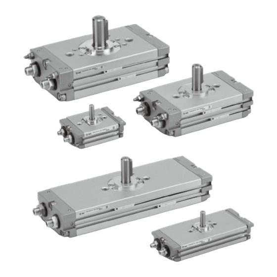
- Page 1 文書 No.CRQ2-OM00002-C PRODUCT NAME Compact Rotary Actuator MODEL / Series / Product Number CRQ2 Series Rack Pinion Type...
-
Page 2: Table Of Contents
Contents Safety Instructions Page 1.Outline 17 1-1 Specification 17 1-2 18 Effective output 1-3 Rotation range 18 2.Internal structure and parts description 19 2-1 Size 10,15 19 2-2 Size 20,30,40 20 3.Basic circuit of the rotary actuator 21 3-1 Circuit structure 21... -
Page 3: Safety Instructions
Safety Instructions These safety instructions are intended to prevent hazardous situations and/or equipment damage. These instructions indicate the level of potential hazard with the labels of “Caution,” “Warning” or “Danger.” They are all important notes for safety and must be followed in addition to International Standards (ISO/IEC) , and other safety regulations. - Page 4 Safety Instructions Caution 1.The product is provided for use in manufacturing industries. The product herein described is basically provided for peaceful use in manufacturing industries. If considering using the product in other industries, consult SMC beforehand and exchange specifications or a contract if necessary. If anything is unclear, contact your nearest sales branch.
- Page 5 Design / Selection Warning 1. Confirm the specifications. Products represented in this catalog are designed only for use in compressed air systems. Do not operate at pressures or temperatures, etc., beyond the range of specifications, as this can cause damage or malfunction. (Refer to the specifications.) Please contact SMC when using a fluid other than compressed air.
- Page 6 12. Select a speed within the product’s allowable energy value. If the product’s kinetic energy of the load exceeds the allowable value, it could damage the product, and cause a hazard to humans and damage the machinery and equipment. 13. Provide a shock absorber if the kinetic energy that is applied to the product exceeds the allowable value.
- Page 7 Mounting Warning 1. Operation manual Install the product and operate it only after reading the operation manual carefully and understanding its contents. Also, keep the manual in a location where it can be referred to as necessary. 2. Ensure sufficient space for maintenance activities. When installing the products, allow access for maintenance.
- Page 8 12. Place an external stopper in a position that is away from the rotating table. If the stopper is placed near the rotating table, the torque that is generated by the product itself will cause the reaction force which is directed to the stopper to be redirected and applied to the rotating table. This will lead to the breakage of the rotating table and bearing.
- Page 9 Caution 1. Do not use organic solvent to wipe the area of the name plate that shows the model. It will erase what is indicated on the name plate. 2. Do not hit the rotating table by securing the body or hit the body by securing the rotating table.
- Page 10 Lubrication Warning 1. This product should be used without lubrication. Although it will operate even if it is lubricated, it could lead to sticking or slipping. Air Supply Warning 1. Type of fluids Please consult with SMC when using the product in applications other than compressed air. 2.
- Page 11 Operating Environment Warning 1. Do not use in an atmosphere having corrosive gases, chemicals, sea water, water, steam, or where there is direct contact with any of these. Refer to the construction for information on the rotary table material. 2. Do not expose the product to direct sunlight for an extended period of time. 3.
- Page 12 Auto Switches Precautions Design / Selectio Warning 1. Confirm the specifications. If the product is used with excess load applied or beyond the specification range, this may cause the product to break or malfunction. We do not guarantee against any damage if the product is used outside of the specification range.
- Page 13 8. Keep wiring as short as possible. <Reed> As the length of the wiring to a load gets longer, the rush current at switching ON becomes greater, and this may shorten the product’s life. (The switch will stay ON all the time.) 1) Use a contact protection box when the wire length is 5m or longer.
- Page 14 11. Pay attention to leakage current. <2-wire type> Current (leakage current) flows to the load to operate the internal circuit even when in the OFF state. > Operating current of load (OFF condition) Leakage current If the criteria given in the above formula are not met, it will not reset correctly (stays ON).Use a 3-wire switch if this specification will not be satisfied.
- Page 15 6. Check the actual actuation status and adjust the auto switch mounting position. According to the installation environment, the rotary table may not operate even at its proper mounting position. Even when setting at a midpoint of the stroke, check the actuation status and make the adjustment in the same manner.
- Page 16 7. Avoid incorrect wiring. <Reed> A 24 VDC auto switch with indicator light has polarity. The brown lead wire or terminal No.1 is (+), and the blue lead wire or terminal No.2 is (-). 1) If connections are reversed, an auto switch will operate, however, the light emitting diode will not light Also, take note that a current greater than that specified will damage a light emitting diode and it will no longer operate.
- Page 17 2. Do not use in an environment where the auto switch will be continually exposed to water. Although auto switches satisfy IEC standard IP67 construction expect some models (D-A3□, A44□, G39□, K39□, RNK, RPK) do not use auto switches in applications where continually exposed to water splash or splay.
- Page 18 Caution 1. Perform the following maintenance periodically in order to prevent possible danger due to unexpected auto switch malfunction. 1) Secure and tighten auto switch mounting screws. If screws become loose or the mounting, position is dislocated, retighten them after readjusting the mounting position.
-
Page 19: 1.Outline
1. Outline This operation manual explains “rack and pinion type compact rotary actuator”. hen using the product, load (moment of inertia), rotation time and other factors have to be considered. So, confirm the specification of the product prior to use. 1-1 Specifications Table1 Specification-1 Size... -
Page 20: 1-2 Effective Output
1-2 Effective output Fig.1 Effective output 1-3 Rotation range When pressurized from the Port A, the shaft will rotate clockwise. Flat face and parallel key position indicate B port is pressurized. Key or flat B Port A Port Angle adjustment ± 5 ° Rotation range:90°... -
Page 21: 2.Internal Structure And Parts Description
2.Internal structure and parts description 2-1 Size 10,15 24 Heat transferred label 23 Seal washer 22 Cushion pad 21 Piston packing 20 End cover gasket 19 Cover gasket 18 Packing 17 Retainer 16 Bearing 15 Cross recessed No.0 screw 14 Cross recessed No.0 screw 13 Hexagon socket head screw 12 Adjust bolt Small hexagon nut... -
Page 22: 2-2 Size
2-2 Size 20,30,40 26 Heat transferred label No cushion :4pcs., with cushion: 6pcs. 25 Steel ball 24 Seal washer 23 Cushion packing Only cushion type included 22 Piston packing 21 Gasket 20 Packing 19 Retainer 18 Parallel key 17 Bearing 16 Cushion valve Ass’y Only cushion type included 15 Cross recessed No.0 screw... - Page 23 3.Basic circuit 3-1 Circuit structure The standard circuit for operating a rotary cylinder with an air filter, regulator, solenoid valve and speed controller is shown in Figure 1 below. Regulator Speed controller Air filter Solenoid valve Rotary actuator Fig.2 Basic circuit 3-2 Recommended models Table 4 shows recommended solenoid valve, speed controller, tube for the basic circuit in Fig.2.
-
Page 24: 4.Mounting
4.Mounting 4-1 Restriction of the load to axis Table of load below shows the allowable load when no moving load applied to axis direction. Avoid applying load to the axis directly as much as possible. (N) Table5 Allowable load Load direction Size ※Fr 15.7... -
Page 25: O P E R A T I O N O F A X I S F I T T I N G R E F E R R I N
b)Mind so that the piping swarf and sealing material do not enter into the piping when screwing in piping and fitting. When using the seal tape, leave 1.5~2 threads. 4-5 Operating air Air supplied to the rotary actuator shall be cleaned by the filter. CRQ2 series is lubrication free. Sealant tape Winding direction Expose approx. -
Page 26: 5.Setting Rotation Time
5.Setting rotation time The load inertia lead to cause the damage of the shaft and internal parts even if generated torque of rotary actuator is small. The calculation of load inertia moment and kinetic energy is necessary to set the rotation time for operating the rotary actuator. - Page 27 Table for calculation of Inertia moment -25-...
-
Page 28: K I N E T I C E N E R G
5-2 Kinetic energy Table 8 shows the allowable kinetic energy of the rotary actuator. The end angular speed ω is obtained by: Table8 Allowable kinetic energy Allowable kinetic energy mJ Size Cushion angle No cushion Cushion type - - 0.25 -... -
Page 29: E X T E R N A L S T O P P E
Fig. 11 5-3-2 Caution on using external stopper Angle adjustment is available for CRQ2 series rotary actuator. Mind so that the hexagon socket set screw (angle adjusting screw) does not collide into the piston. -27-... -
Page 30: A U T O S W I T C H S P E C I F I C A T I O
6.Rotary actuator with auto switch The piston of rotary actuator with auto switch is attached with magnet on it, and equipped with auto switch outside to detect the piston position (shaft flat face and key groove position). 6-1 Auto switch specification Load voltage Lead wire length(m)... -
Page 31: A U T O S W I T C H I N S T A L L A T I O
6-2 Auto switch installation Use small driver (5~6mm of grip diameter ) to tighten auto switch set screws with 0.1~0.2N・m of tightening torque. se slotted setscrew (with urethane damper) as setscrew. Fig.12 6-3 Auto switch set position Operation range at optimum set position (Lm/2) Most sensitive position Auto switch... -
Page 32: I N T E R N A L S T R U C T U R E A N D O P E R A T I O N P R I N C I P L
6-4 Internal structure and operation principle Most sensitive position Most sensitive position Piston A Switch A Switch A Operating range Operating range Port A Piston B Magnet Magnet Fig.14 In figure 14, the switch A is turned on. When pressurized from port A, piston B moves to the left and piston A moves to the right, and the shaft rotates clockwise. -
Page 33: 8.Maintenance・Inspection
8.Maintenance・Inspection Periodic inspection is necessary for optimum use. Generally, annual inspection is recommended for the rotary actuator. Even if no problem is found, seal parts replacement is recommended every three years. It is highly possible that the actuator is operated out of specification when the components like shaft, pinion, rack, bearing are broken. -
Page 34: D I S A S S E M B L I N G P R O C E D U R
8-2-2 Disassembling procedure (1) Loosen cross recessed no.0 screw(size 10,15)or roundhead screw(size 20,30,40). (2) Pull out the bearing retainer and the shaft from the body. Remove the bearing from the housing at this time. (3) Loosen hexagon socket head bolt to remove the cover Ass’y and the end cover Ass’y. -
Page 35: A S S E M B L E P R O C E D U R
8-2-3 Assemble procedure (1) Clean parts thoroughly before assembling to remove dust. Apply grease to parts where specified in table 11 so that the surface become glossy (Not too much!). Don’t damage the packing when attaching the piston packing to the piston. Table 11 Parts applied with grease Grease applied parts Grease... - Page 36 End cover Ass'y End cover gasket End cover Adjust bolt Ass’y Size 10,15 Gasket Cushion packing End cover Cushion valve Ass’y Adjust bolt Ass’y Size 20,30,40 (with cushion) Fig.19 Insert and attach the cushion packing and the packing with the direction in the drawing below. Inse ection Side(Cross nutsection)...
- Page 37 Shaft Pinion gear It greases it to extent where the ditch of the gear is buried. Fig.22 (2) Set the bearing to the housing of the body, and insert the piston Ass’y to the body. Since the piston packing goes through the bearing housing, insert the piston Ass’y slowly pressing the packing inside so that packing is not gouged.
- Page 38 (3) Mount the cover and the end cover, and push the piston Ass’y and the cover until they touch the end cover as in Fig.24 Adjust the hexagon socket head set screw (adjust bolt) so that the screw does not contact with the piston Ass’y.
-
Page 39: T R O U B L E S H O O T I N
8-3 Troubleshooting Problem Possible cause Solution Supply pressure is not applied Correctly set the regulator at the supply correctly. pressure side. The directional switching Correctly apply a signal to the directional valve (such as a solenoid switching valve (such as a solenoid valve). valve) does not switch. - Page 40 Problem Possible cause Solution Air leakage from the The seal parts need to be replaced. Piston seal is worn out. table Contact SMC. Replace the rotary table with the new one. After that, take the measures below. ・Calculate the kinetic energy applied to the rotary table and adjust the load and rotation speed to make the value within the allowable kinetic energy.
- Page 41 Revision history A: 360° specification added B: Grease name change C: Changed Hexagon nut with flange to Small hexagon nut Add tightening torque Move to new format 4-14-1, Sotokanda, Chiyoda-ku, Tokyo 101-0021 JAPAN Tel: + 81 3 5207 8249 Fax: +81 3 5298 5362 https://www.smcworld.com Note: Specifications are subject to change without prior notice and any obligation on the part of the manufacturer.
Need help?
Do you have a question about the CRQ2 Series and is the answer not in the manual?
Questions and answers