Advertisement
Quick Links
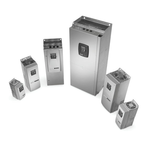
AGSVX9000 Drives
Quick Setup Guide
Effective May 2013
New Information
CONTENT
STEP 1 — Keypad Operation Overview
STEP 2 — Standard Wiring Diagrams and Connections
STEP 3 — Start-Up Wizard
STEP 4 — Operating and Programming Menu
Navigation
STEP 5 — Faults and Warning Indication
STEP 6 — Monitoring Menu
Advertisement

Related Manuals for Eaton AGSVX9000


Summary of Contents for Eaton AGSVX9000
- Page 1 AGSVX9000 Drives Quick Setup Guide Effective May 2013 New Information CONTENT STEP 1 — Keypad Operation Overview STEP 2 — Standard Wiring Diagrams and Connections STEP 3 — Start-Up Wizard STEP 4 — Operating and Programming Menu Navigation STEP 5 — Faults and Warning Indication...
-
Page 2: Keypad Operation Overview
LCD Status Indicators Indicator Description Indicates that the AGSVX9000 is running and controlling the load. Blinks when a stop command has been given but the AGSVX9000 is still ramping down. Counterclockwise Operation The output phase rotation is BAC, corresponding to counterclockwise rotation of most motors. -
Page 3: Menu Navigation
Used to set the password (if defined) when leaving the “Operate” menu. • scroll through the “Active Faults” menu when the AGSVX9000 is stopped. Menu Navigation Navigation Tips To navigate within one level of a menu, use the up and down arrows. - Page 4 1 – 15 hp 480V 1-1/2 – 30 hp Control Board L2 L3 (Optional) External External RFI-Filter Filter (Optional) (Optional) L2 L3 AGSVX9000 Power and Motor Wiring for Low Horsepower Drives (1 – 30 hp) AGSVX9000 Drives MN040001EN—May 2013 www.eaton.com...
- Page 5 20 – 30 hp 480V 40 – 250 hp Control Board L2 L3 (Optional) External External RFI-Filter Filter (Optional) (Optional) L2 L3 AGSVX9000 Power and Motor Wiring for Large Horsepower Drives (20 – 250 hp) AGSVX9000 Drives MN040001EN—May 2013 www.eaton.com...
- Page 6 Jumper Block X3: CMA and CMB Grounding CMB connected to GND CMA connected to GND CMB isolated from GND CMA isolated from GND CMB and CMA internally connected together, isolated from GND = Factory default. AGSVX9000 Drives MN040001EN—May 2013 www.eaton.com...
-
Page 7: Startup Wizard
Parameter Number Parameter Name Desired Setting P1.2.1.1 Start Mode Start P–Stop P P1.2.7 .2 Start 2 DigIn:A.2 P1.2.7 .3 Run Enable DigIn:A.3 P1.2.7 .10 Fault Reset DigIn:0.1 P1.3.3.2 DigOut:B.1 P5.7 .2 Fan Control Calc Temp AGSVX9000 Drives MN040001EN—May 2013 www.eaton.com... -
Page 8: Main Menu Navigation
O1 Output Frequency–0.0 Hz O2 Freq Reference–0.0 Hz ..Note: Enter Key — Holding the “Enter” key for more than 3 seconds will allow you to go directly to the programming mode. AGSVX9000 Drives MN040001EN—May 2013 www.eaton.com... - Page 9 To exit the Operate Menu to access the other menus, depress the ENTER button for 2 seconds. While in the other menus, if there is no keypad activity, the display will return to the Operate Menu after 30 seconds. AGSVX9000 Drives MN040001EN—May 2013 www.eaton.com...
- Page 10 Local Reference Keypad P1.1.14 Remote Reference Keypad P1.2.1.1 Start Mode Start P–Stop P P1.2.7 .2 Start 2 DigIn:A.2 P1.2.7 .3 Run Enable DigIn:A.3 P1.2.7 .10 Fault Reset DigIn:0.1 P1.3.3.2 DigOut:B.1 P5.7 .2 Fan Control Calc Temp AGSVX9000 Drives MN040001EN—May 2013 www.eaton.com...
- Page 11 Menus M3 to M6 provide information on the Active Faults, Fault History, System Menu settings and the Expander Board setup. These menu items are explained in detail in Chapter 5 of the SVX9000 User Manual. AGSVX9000 Drives MN040001EN—May 2013 www.eaton.com...
- Page 12 Brake chopper Control unit Slot fault supervision AGSVX9000 Device change PT100 board undertemperature temperature fault (same type) AGSVX9000 Device added — — overtemperature (same type) Motor stalled Device removed — — AGSVX9000 Drives MN040001EN—May 2013 www.eaton.com...
- Page 13 Monitored Menu Items shown in the table above. Use the right arrow key to select the item to be modified and then the up or down arrow keys to select the new item. Press the ENTER key to accept the change. AGSVX9000 Drives MN040001EN—May 2013 www.eaton.com...
- Page 14 Our focus is on delivering the right solution for the application. But, decision makers demand more than just innovative products. They turn to Eaton for an unwavering commitment to personal support that makes customer success a top priority. For more information, visit www.eaton.com/electrical.
Need help?
Do you have a question about the AGSVX9000 and is the answer not in the manual?
Questions and answers