Table of Contents
Advertisement
Quick Links
®
User Manual for PuraLev
iF100SU
www.levitronix.com
®
PuraLev
iF100SU
USER MANUAL
®
This manual contains information necessary for the safe and proper use of the PuraLev
iF100SU. Included are
specifications for the standard configurations of the flow control system and instructions regarding its use, installation,
operation, adjustment, inspection and maintenance. For special configurations of the flow control system refer to
®
accompanying information. If the flowmeters must be configured for other parameter settings, then the Levitronix
Service Software version V2.0.7.0 (with according manual Levitronix
Doc.# PL-4047-00) is needed. Familiarize
yourself with the contents of the manual to ensure the safe and effective use of this product. After reading this
manual, please store the manual where the personnel responsible for operating the flow control system can readily
refer to it at any time.
First Release: 29-Oct-2020
PL-4079-00, Rev00, DCO# 21-271
Last Update: 03-Dec-2021
Advertisement
Table of Contents

Related Manuals for Levitronix PuraLev iF100SU


Summary of Contents for Levitronix PuraLev iF100SU
- Page 1 For special configurations of the flow control system refer to ® accompanying information. If the flowmeters must be configured for other parameter settings, then the Levitronix Service Software version V2.0.7.0 (with according manual Levitronix Doc.# PL-4047-00) is needed.
-
Page 2: Table Of Contents
® User Manual for PuraLev iF100SU www.levitronix.com Table of Contents SAFETY PRECAUTIONS ................................3 SPECIFICATIONS ..................................4 Specification of Components ..............................4 System Overview and General Specification ......................... 6 General Environmental Conditions ............................8 Pressure-Flow Curves ................................8 Maximum Static Pressure for Pump Heads ........................... 9 Flow Control Specifications .............................. -
Page 3: Safety Precautions
Installation shall be done by qualified personnel only. Following safety precautions and all “CAUTION”, “WARNING” and “DANGER” indications in the relevant sections shall be followed. CAUTION ® Do not under any circumstances open the driver. Levitronix does not assume responsibility for any damage, which occurs under such circumstances. CAUTION High magnetic field strength of pump impeller. -
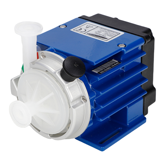
Page 4: Specifications
® User Manual for PuraLev iF100SU www.levitronix.com 2 Specifications 2.1 Specification of Components Figure 1: Flow control system with standard main components Figure 2: General standard accessories Figure 3: Standard cables PL-4079-00, Rev00, DCO# 21-271... - Page 5 Note 2: Gamma irradiated and sterile fittings version available (see product literature for PuraLev-i200SU). Pos. Component Article Name Article # Fitting Wet Material Note Triclamp 3/8” LFS-06SU-Z (8 lpm) 100-30377 See Levitronix ® technical brochure of Polypropylene (FDA, USP Class VI, ® Triclamp 3/8” LFS-06SU-Z-SC1 100-30394 LEVIFLOW Single- LFS-SU single-use sensor series for...
-
Page 6: System Overview And General Specification
® User Manual for PuraLev iF100SU www.levitronix.com 2.2 System Overview and General Specification 2.2.1 System Configuration for Stand-Alone Model Figure 4 illustrates the system configuration of the Stand-Alone model with integrated user panel and buttons to set the flow manually. The driver also contains a PLC interface for remote control by analog and digital signals. - Page 7 A RS485 (Modbus) enables communication with a user panel or a ® PC with the Levitronix Service Software. Hence parameterization, firmware updates and failure analysis are possible. The RS485 can also be used as a fieldbus to implement more intelligent concepts of pump control.
-
Page 8: General Environmental Conditions
® User Manual for PuraLev iF100SU www.levitronix.com 2.3 General Environmental Conditions Usage Indoor Altitude Up to 2000 m Operating ambient temperature 0 to 40 °C -20 to 80 °C Storage ambient temperature -20 to 70 °C for single-use pump head (Extremes for Transportation) 15 –... -
Page 9: Maximum Static Pressure For Pump Heads
® User Manual for PuraLev iF100SU www.levitronix.com 2.5 Maximum Static Pressure for Pump Heads [°F] Safety Factor = 1.3 (according to EN12162) Limitation: Given by deformation. Burst pressure is significantly higher Ambient Temp = 25 C Note: Pressure limit only valid for pumphead mounted on motor. Values only valid after Gamma radiation doses of <... -
Page 10: Basic Dimensions Of Main Components
® User Manual for PuraLev iF100SU www.levitronix.com 2.7 Basic Dimensions of Main Components Inlet/Outlet Fitting: 1/2“ Triclamp Clamp OD = 25mm for Mini-Clamp ½” Bore ID = 9.4 mm for typical tubing ID 3/8” Standard: ASME BPE 2009 Figure 10: Basic dimensions (in [mm] and [inch]) of Stand-Alone model Note 1: Drawings with DCP-200.3 (Barb) and DCP-200.3-SF1 (Sterile Fittings) are available on request. - Page 11 ® User Manual for PuraLev iF100SU www.levitronix.com Inlet/Outlet Fitting: 1/2“ Triclamp Clamp OD = 25mm for Mini-Clamp ½” Bore ID = 9.4 mm for 3/8” ID tubing Not configured connections protected by sealed covers. Standard: ASME BPE 2009 Figure 12: Basic dimensions (in [mm] and [inch]) of OEM model Note 1: Drawings with DCP-200.3 (Barb) and DCP-200.3-SF1 (sterile fittings) are available on request.
- Page 12 ® User Manual for PuraLev iF100SU www.levitronix.com IPS Cable Power ICP-1.1 (for EasyConnect and Stand-Alone drivers) IPS Cable Signal ICS-1.1 (for EasyConnect drivers) Wire size: 0.08 mm Wire size: 0.5 mm to driver fieldbus IN to driver fieldbus OUT to AC/DC Supply...
-
Page 13: Engineering Information
(see explanation in Section 3.3). For the EasyConnect and OEM models the warning signal ® can be monitored with the Levitronix Service Software or configured on one of the digital outputs. For the Stand-Alone model the temperature can be monitored on the display. -
Page 14: Thermal Management
® User Manual for PuraLev iF100SU www.levitronix.com 3.3 Thermal Management The driver temperature depends on the ambient and liquid temperature, as well as on the hydraulic operation point. Figure 16 and Figure 17 illustrate the temperature characteristics of the motor depending on these parameters. - Page 15 ® User Manual for PuraLev iF100SU www.levitronix.com The above curves are measurements of the motor temperature at certain liquid and ambient temperatures. The equation below shows how to calculate the motor temperature for other liquid and ambient temperatures based on these curves.
-
Page 16: Hydraulic Circuit Design
9. At higher liquid temperature rules mentioned above become more important due to higher cavitation tendency of the liquid. ® Contact the Levitronix Technical Service department (see Section 8) for more detailed considerations and support on the design of the hydraulic circuit. -
Page 17: Installation
® User Manual for PuraLev iF100SU www.levitronix.com 4 Installation 4.1 Electrical Installation of Stand-Alone Model 4.1.1 Overview of Connections and Designations User Button Display PLC Connector Power Supply Connector Flow Sensor Connector Figure 18: Electrical connections to Stand-Alone driver IPD-100.6... - Page 18 ® User Manual for PuraLev iF100SU www.levitronix.com 4.1.2 Overview Electrical Schematics of Driver Interface Levitronix Driver Example of User Interface Circuit Interface Circuit Pin 2: Digital Input 2.2 k 5..24 V Pin 4: Common Digital Input Pin 6: Analog Input 450 ...
- Page 19 Consult Figure 15 to get the power consumption ® depending on the flow. If power supplies are used other than the one defined by Levitronix , it is highly recommended to test these under dynamic conditions (acceleration and braking of the pump rotor speed).
-
Page 20: Electrical Installation Of Easyconnect Model
Not connected pink-blue For remote control with other devices. RS485+ white RS485+ ® Fieldbus Modbus protocol. Usage of Levitronix Service Software with a RS485- RS485- yellow RS485 to USB adaptor cable (see Table 4). Internal Internal grey Do not Internal bus needed to connect pumps for serial pumping. - Page 21 (Current Input) Speed limit = 9000 rpm The designation of the analog inputs can be Speed) Cutt-off speed = 0 rpm ® changed with Levitronix Service Software. Analog voltage input: 0 – 10V (7.9 kOhm, no galvanic isolation). grey- Configurable as Analog Input Note: Max.
- Page 22 ® User Manual for PuraLev iF100SU www.levitronix.com 4.2.2 Overview Electrical Schematics of Driver Interface Levitronix Driver Interface Circuit Example of User Interface Circuit Pin 5: Digital Input 1 2.2 k Pin 4: Digital Input 2 5..24 V 2.2 k Pin 3: Common Digital Input Pin 7: Analog Input 1 450 ...
- Page 23 Figure 22 shall be used to have a stable communication and avoid disturbance effects. The ® RS485 (Modbus RTU) protocol for master communication is available at Levitronix on request. The Fieldbus OUT interface can be used to feed through the RS485 bus to other devices.
- Page 24 Technical Service department (see Section 8) for details and support. ➔ ® Address setting of the pump units can be done with the Levitronix Service Software and a PC. A USB/RS485 converter cable with integrated initialization network can be ordered according to Table 4 ➔...
-
Page 25: Electrical Installation Of Oem Model
Table 15: Signals of the driver cable with designation for standard firmware Note 1: For other configurations of PLC Inputs and Outputs refer to alternate firmware documentation ® Note 2: Configurations can be done with Levitronix Service Software Note 3: Power wires (P+, P-) have cross section 1.5 mm and all others 0.14 mm... - Page 26 ® User Manual for PuraLev iF100SU www.levitronix.com 4.3.2 Overview Electrical Schematics of OEM Driver Interface Cable Wires (UL Cable) Example of User Levitronix Driver Colours/Designation Interface Circuit Interface Circuit Pink: Digital Input 1 2.2 k 5..24 V Grey: Digital Input 2 2.2 k...
- Page 27 For usage of the RS485 as a control or service interface, an initialization resistor network according to Figure 24 or Figure 25 shall be used in order to have a stable communication and avoid disturbance effects. The ® RS485 Modbus RTU protocol for master communication is available at Levitronix on request. ®...
-
Page 28: Electrical Installation Of Flow Sensor
Technical Service department (see Section 8) for details and support. ® ➔ Address setting of the pump units can be done with the Levitronix Service Software and a PC. A USB/RS485 converter cable with integrated initialization network can be ordered according to Table 4. -
Page 29: Mechanical Installation Of Driver With Pump Head
® User Manual for PuraLev iF100SU www.levitronix.com 4.5 Mechanical Installation of Driver with Pump Head WARNING The driver is not rated to be placed next to flammable gases. Do not use the driver next to flammable gases without adequate safety precautions to fulfill the relevant regulatory requirements. -
Page 30: Mechanical Installation Of Flow Sensor
1. For mounting and exchanging the sensors and assure proper operation it is recommended to use the LMK mounting ® kits, which can be ordered according to Table 4. Contact Levitronix for detailed drawing specifications. 2. Alternatively, the sensor body can be mounted with the fixation holes as shown in Figure 13. -
Page 31: Operation
® User Manual for PuraLev iF100SU www.levitronix.com 5 Operation In this section the very basic operation of OEM, EasyConnect and Stand-Alone models is explained. For more extended operation modes and configurations consult the relevant Firmware and Service Software specifications. 5.1 Operation of Stand-Alone Model 5.1.1 Manual Operation... -
Page 32: Operation Of Easyconnect And Oem Model
® User Manual for PuraLev iF100SU www.levitronix.com 5.2 Operation of EasyConnect and OEM Model 5.2.1 Operation with PLC Figure 30 and Figure 31 show the state diagram of the integrated pump and the integrated flowmeter. Power On Status pump: not... - Page 33 10 Hz Zero Adjust is in progress and frozen speed is the speed before Zero Adjust was started. ® Determine type of pump error with Levitronix Service Software or Modbus RTU protocol. Not active Active Integrated pump is in error state.
- Page 34 The states of the integrated pump system are described in the following: Off: ® The pump system is switched off and the impeller is not levitated. In this state, Levitronix Service Software has full control. Flow Control Mode: The pump system is switched ON and the impeller is rotating with the referenced speed from flow controller.
-
Page 35: Zero Adjustment Of Flow Sensor
Technical Department (see Section 8) for detailed protocol specifications. The ® RS485 interface can be used in connection with the USB interface of a PC and the Levitronix Service Software. Various accessory cables are available to connect to the RS485 of the drivers as illustrated in Figure 5 for the EasyConnect model and Figure 7 for the OEM model. -
Page 36: Instructions For Use Of Pump Head
Inspection Prior to Use The pump head should be inspected prior to use CAUTION for any damage. Do not use the pump head if any damage is found. Contact Levitronix ® regarding return of any suspected pump head. Gamma Sterilization The pump heads DCP-200 have been tested to be 6.1.3... -
Page 37: Mounting Of Pump Head
® User Manual for PuraLev iF100SU www.levitronix.com 6.3 Mounting of Pump Head 6.4 Removal of Pump Head 6.3.1 Preparation 6.4.1 Preparation After removal of the pump head from its packaging Set the speed to 0 rpm and disable the system. -
Page 38: Troubleshooting
7.2.3 Troubleshooting with User Panel LUI-B.1 For troubleshooting and failure analysis with the user panel LUI-B.1 the integrated display gives advice about status and potential failure details. 8 Technical Support For troubleshooting, support and detailed technical information contact Levitronix Technical Service Department: Levitronix Technical Service Department Technoparkstr. -
Page 39: Appendix
® User Manual for PuraLev iF100SU www.levitronix.com 9 Appendix 9.1 Regulatory Status 9.1.1 CE Marking ® We herewith declare that the Flow Control System Family PuraLev iF100SU, in its various configurations, is in conformity with the below mentioned European Directives. -
Page 40: Symbols And Signal Words
® User Manual for PuraLev iF100SU www.levitronix.com 9.2 Symbols and Signal Words Symbol / Description Type Source Signal Word Indication of an imminently hazardous situation that, if not DANGER Signal word SEMI S1-0701 avoided, will result in death or severe injury. Limited to the...
Need help?
Do you have a question about the PuraLev iF100SU and is the answer not in the manual?
Questions and answers