AgileX SCOUT MINI User Manual
Hide thumbs
Also See for SCOUT MINI:
- User manual (43 pages) ,
- User manual (27 pages) ,
- User manual (41 pages)
Table of Contents
Advertisement
Quick Links
Advertisement
Table of Contents

Related Manuals for AgileX SCOUT MINI


Summary of Contents for AgileX SCOUT MINI
- Page 1 SCOUT MINI AgileX Robotics Team User Manual 2020.08 V.2.0.0...
- Page 2 If you have any questions about use, please contact us at support@agilex.ai. Please follow and implement all assembly instructions and guidelines in the chapters of this manual, which is very important. Particular...
- Page 3 SCOUT MINI integrators and end customers have the responsibility to ensure compliance with the applicable laws and regulations of relevant countries, and to ensure that there are no major dangers in the complete robot application. This includes but is not limited to the following: 1.Effectiveness and responsibility...
-
Page 4: Table Of Contents
CONTENTS 1. Introduction to SCOUT MINI 3.3.3 Implementation of CAN 1.1 Product list command control 1.2 Performance parameters 3.4 Firmware upgrade 1.3 Requirement for development 4. Attention 2. The Basics 4.1 Battery precautions 2.1 Status indication 4.2 Application environment 2.2 Instructions on electrical interfaces precautions 2.3 Remote control instructions... -
Page 5: Introduction To Scout Mini
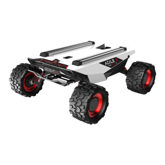
The minimum turning radius of the chassis is 0 m, and the climbing angle is close to 30 degrees. SCOUT MINI is still capable of excellent off-road performance although it is only half of SCOUT in size. -
Page 6: The Basics
12. Front fence Based on the concept of modular and intelligent design as a whole, SCOUT MINI combines filled solid tires with independent suspension as its power module, which, along with powerful hub motor, enables the development platform of SCOUT MINI robot chassis to flexibly move on different ground surfaces with high passing ability and ground adaptability. -
Page 7: Remote Control Instructions
2.3 Remote control instructions FS RC transmitter is an optional feature of SCOUT MINI for users to choose as actually required. With this RC transmitter designed on the left throttle in this product, users can easily control SCOUT MINI universal robot chassis. Its definitions and functions are shown in Figure 2.5 for reference. -
Page 8: Description Of Movement By Remote Control And Control By Command
Figure 3.0 Schematic Diagram of Reference Coordinate System for Vehicle Body As shown in Figure 3.0, the vehicle body of SCOUT MINI is in parallel with X axis of the established reference coordinate system.In the controller mode with RC transmitter, pushing the left rocker of the RC transmitter forward and backward respectively refers to the movement on the positive and negative directions of axis X;... -
Page 9: Getting Started
Basic operating procedure of remote control After SCOUT MINI mobile chassis is started correctly, turn on the RC transmitter and select the remote-control mode. Then, the SCOUT MINI platform motion can be controlled by the RC transmitter. - Page 10 Table 3.1 Feedback Frame of SCOUT MINI Chassis System Status Command Name System Status Feedback Command Sending node Receiving node Cycle (ms) Receive-timeout (ms) Steer-by-wire chassis Decision-making control unit 0x151 20ms None Data length 0x08 Position Function Data type Description...
- Page 11 [1]: The subsequent versions of robot chassis firmware version after [3]: The over-temperature protection of motor drive and the V1.2.8 are supported, but previous versions need to be updated before motor over-current protection will be internally processed. When supported. the temperature of motor drive is higher than the protective [2]: The over-temperature alarm of motor drive and the motor temperature, the drive output will be limited, the vehicle will over-current alarm will not be internally processed but just set in order...
- Page 12 Note 1 - Control mode instructions In case the RC transmitter is powered off, the control mode of SCOUT MINI is defaulted to command control mode, which means the chassis can be directly controlled via command. However, even though the chassis is in command control mode, the control mode in the command needs to be set to 0 x 01 for successfully executing the speed command.
- Page 13 Table 3.5 No. 1 Motor Information Feedback Command Name No. 1 Motor Drive Information Feedback Frame Sending node Receiving node Cycle (ms) Receive-timeout (ms) Steer-by-wire chassis Decision-making control unit 0x200 20ms None Data length 0x08 Position Function Data type Description byte [0] No.
- Page 14 Table 3.7 No. 3 Motor Information Feedback Command Name No. 3Motor Drive Information Feedback Frame Sending node Receiving node Cycle (ms) Receive-timeout (ms) Steer-by-wire chassis Decision-making control unit 0x202 20ms None Data length 0x08 Position Function Data type Description byte [0] No.
- Page 15 Table 3.9 Lighting Control Frame 灯光控制帧 Command Name Sending node Receiving node Cycle (ms) Receive-timeout (ms) Decision-making control unit Steer-by-wire chassis 0x140 25ms 无 Data length 0x08 Position Function Data type Description 0x00 Control command invalid byte [0] Lighting control unsigned int8 enable flag 0x01 Lighting control enable...
-
Page 16: Can Interface Protocol
Figure 3.2. Users need to lead wires out by welding on their own. For wire definitions, please refer to Table 2.2 Note: In the current SCOUT MINI version, only the top interface is open to external extension. The maximum current that can be provided in this RED :VCC(Positive pole) version is 5A.. -
Page 17: Firmware Upgrade
3.4 Firmware upgrade To facilitate the customer's upgrading of the firmware version Connect the serial cable to the computer; used by SCOUT MINI and bring the customer a better Open the client software; experience, SCOUT MINI provides a hardware interface for the Select the port number;... -
Page 18: Attention
4 Attention This Section includes some precautions that should be paid attention to for SCOUT MINI use and development. 4.2 Application environment precautions 4.1 Battery precautions The operating temperature of SCOUT MINI outdoors is -10℃ to 45 The battery supplied with SCOUT MINI is not always fully charged ℃;... - Page 19 Q: Is the tire wear of SCOUT MINI is normally seen when it is running? A: The tire wear of SCOUT MINI is normally seen when it is running. As SCOUT MINI is based on the four-wheel differential steering design, sliding friction and rolling friction both occur when the vehicle body rotates.
-
Page 20: Product Dimensions
6 Product Dimensions 6.1 Illustration diagram of product external dimensions... - Page 21 AgileX Robotics ( Dongguan) CO., Ltd WWW.AGILEX.AI Email: sales@agilex.ai TEL:+86-0769-22892150...
Need help?
Do you have a question about the SCOUT MINI and is the answer not in the manual?
Questions and answers