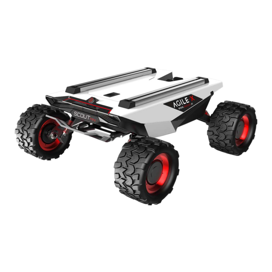
AgileX SCOUT MINI User Manual
Hide thumbs
Also See for SCOUT MINI:
- User manual (43 pages) ,
- User manual (41 pages) ,
- User manual (24 pages)

Subscribe to Our Youtube Channel
Related Manuals for AgileX SCOUT MINI


Summary of Contents for AgileX SCOUT MINI
- Page 1 20192 AgileX Robotics SCOUT MINI User Manual AgileX Robotics Support Team Version 1.0 Release...
- Page 2 AgileX robotics (Dongguan) Co., Ltd. Description of Version Information Version Content of Changes Person in Charge Date v1.0.0 [New addition]Create a file Xie Zhiqiang November 22, 2019 1 / 27...
-
Page 3: Table Of Contents
AgileX robotics (Dongguan) Co., Ltd. CONTENTS 1. Introduction to SCOUT MINI ........................3 1.1 Product list ............................3 1.2 Performance parameters ........................3 1.3 Requirement for development ......................4 2. The Basics ..............................5 2.1 Status indication ..........................5 2.2 Instructions on electrical interfaces ....................6 2.3 Remote control instructions ...................... -
Page 4: Introduction To Scout Mini
The minimum turning radius of the chassis is 0 m, and the climbing angle is close to 30 degrees. SCOUT MINI is still capable of excellent off-road performance although it is only half of SCOUT in size. In addition, it has a breakthrough high-speed, accurate, stable and controllable dynamic control system up to 20 km/h. -
Page 5: Requirement For Development
FS RC transmitter is provided optionally in the factory settings of SCOUT MINI and it allows users to control the mobile chassis to move and turn; the CAN provided on SCOUT MINI can be used for secondary development via the CAN interface. -
Page 6: The Basics
6. Tail light off 12. Front fence Based on the concept of modular and intelligent design as a whole, SCOUT MINI combines filled solid tires with independent suspension as its power module, which, along with powerful hub motor, enables the development platform of SCOUT MINI robot chassis to flexibly move on different ground surfaces with high passing ability and ground adaptability. -
Page 7: Instructions On Electrical Interfaces
Power switch Charging interface SCOUT MINI aviation extension interface is configured with both a set of power supplies and a set of CAN communication interfaces. These interfaces can be used to supply power to extended devices and establish communication. The specific definitions of pins are shown in Figure 2.4. -
Page 8: Description Of Movement By Remote Control And Control By Command
Figure 3.0 Schematic Diagram of Reference Coordinate System for Vehicle Body As shown in Figure 3.0, the vehicle body of SCOUT MINI is in parallel with X axis of the established reference coordinate system. -
Page 9: Instructions On Lighting Control
X to the negative direction of axis Y. 2.5 Instructions on lighting control Lights are mounted in front and at back of SCOUT MINI, and the lighting control interface of SCOUT MINI is open to the users for convenience. Meanwhile, another lighting control interface is reserved on the RC transmitter for energy saving. - Page 10 AgileX robotics (Dongguan) Co., Ltd. Note on mode control: Toggling SWC lever respectively to bottom, middle and top positions refers to normally closed mode, normally open mode and breathing light mode. 9 / 27...
-
Page 11: Getting Started
AgileX robotics (Dongguan) Co., Ltd. 3. Getting Started This Section mainly introduces the basic operation and use of the SCOUT MINI platform and also introduces how to conduct secondary development of the vehicle body via the external CAN ports and CAN bus protocol. -
Page 12: Charging
AgileX robotics (Dongguan) Co., Ltd. 3.2 Charging SCOUT MINI is equipped with a 10 A charger by default to meet customers' charging demand. The detailed operating procedure of charging is shown as follows: Make sure SCOUT MINI chassis is in power-off state. - Page 13 AgileX robotics (Dongguan) Co., Ltd. lower 8 bits Failure information byte [4] higher 8 bits 【 】 unsigned int16 See notes for details Failure information byte [5] lower 8 bits Count parity bit 0 - 255 counting loops, which will be added...
- Page 14 AgileX robotics (Dongguan) Co., Ltd. to decrease. This flag bit will be restored to normal condition as the temperature decreases, and the over-current alarm will be actively cleared once the current value is restored to normal condition; [3]: The over-temperature protection of motor drive and the motor over-current protection will be internally processed.
- Page 15 (checksum) Note 1 - Control mode instructions In case the RC transmitter is powered off, the control mode of SCOUT MINI is defaulted to command control mode, which means the chassis can be directly controlled via command. However, even though the chassis is in command control mode, the control mode in the command needs to be set to 0 x 01 for successfully executing the speed command.
- Page 16 AgileX robotics (Dongguan) Co., Ltd. 0x08 Clear motor over-current failure Note 3 - Example data: The following data is only used for testing 1. The vehicle moves forward at 0.5m/s. byte [0] byte [1] byte [2] byte [3] byte [4]...
- Page 17 AgileX robotics (Dongguan) Co., Ltd. Table 3.5 No. 1 Motor Information Feedback Command No. 1 Motor Drive Information Feedback Frame Name Receive-timeout Sending node Receiving node Cycle (ms) (ms) Steer-by-wire Decision-making 0x200 20ms None chassis control unit Data length 0x08...
- Page 18 AgileX robotics (Dongguan) Co., Ltd. No.2 drive Actual temperature (with an accuracy of byte [4] signed int8 temperature 1℃) No. 2 motor Actual temperature (with an accuracy of byte [5] signed int8 temperature 1℃) Count parity bit 0 - 255 counting loops, which will be added...
- Page 19 AgileX robotics (Dongguan) Co., Ltd. No. 4 drive current byte [0] higher 8 bits Actual current X 10 (with an accuracy of unsigned int16 No. 4 drive current 0.1A) byte [1] lower 8 bits No. 4 drive byte [2] rotational speed...
- Page 20 AgileX robotics (Dongguan) Co., Ltd. Table 3.10 Lighting Control Feedback Frame Command Name Lighting Control Feedback Frame Receive-timeout Sending node Receiving node Cycle (ms) (ms) Steer-by-wire Decision-making 0x141 20ms None chassis control unit Data length 0x08 Position Function Data type...
-
Page 21: Can Cable Connection
Figure 3.1 CAN Message Check Algorithm 3.3.2 CAN cable connection Two aviation male plugs are supplied along with SCOUT MINI as shown in Figure 3.2. Users need to lead wires out by welding on their own. For wire definitions, please refer to Table 2.2. - Page 22 Upgrade procedure: Before connection, ensure the robot chassis is powered off; Connect the serial cable onto the serial port at tail end of SCOUT MINI chassis; Connect the serial cable to the computer; Open the client software;...
- Page 23 AgileX robotics (Dongguan) Co., Ltd. Figure 3.3 Client Interface of Firmware Upgrade 22 / 27...
-
Page 24: Attention
The operating temperature of SCOUT MINI outdoors is -10℃ to 45℃; please do not use it below -10℃ and above 45℃ outdoors; The operating temperature of SCOUT MINI indoors is 0℃ to 42℃; please do not use it below 0℃ and above 42℃ indoors; ... -
Page 25: Precautions For Mechanical Load
4.4 Precautions for mechanical load 4.5 Other notes SCOUT MINI has plastic parts in front and rear, please do not directly hit those parts with excessive force to avoid possible damages; When handling and setting up, please do not fall off or place the vehicle upside down;... -
Page 26: Q&A
Is the tire wear of SCOUT MINI is normally seen when it is running? The tire wear of SCOUT MINI is normally seen when it is running. As SCOUT MINI is based on the four-wheel differential steering design, sliding friction and rolling friction both occur when the vehicle body rotates. -
Page 27: Product Dimensions
AgileX robotics (Dongguan) Co., Ltd. 6. Product Dimensions 6.1 Illustration diagram of product external dimensions 26 / 27...
Need help?
Do you have a question about the SCOUT MINI and is the answer not in the manual?
Questions and answers